Is there anyone who has installed Solidworks on their computer but doesn’t know how to use it?
In this article, we will explain the basic operations and usage of Solidworks in an easy-to-understand manner.
What is “Solidworks”?
Due to its versatility and ease of use, SolidWorks is used in many different academic settings such as universities as well as industrial settings. What makes SolidWorks so versatile is its diverse and complex range of features and tools that give the user the opportunity to model anything that comes to mind. The important thing to note when using SolidWorks or considering purchasing SolidWorks is that it is not a tool that should be used to model something in an artistic fashion.
Let’s start Solidworks
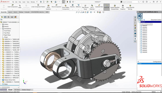
When starting up SolidWorks you will be presented with three modes to work within; Part, Assembly and Drawing, these modes correspond to the file type you will use.
- Part – This option gives the user the opportunity to create singular parts that make up a larger entity, draw sketches or extrude surfaces
- Assembly – This mode allows you to combine the various parts you have generated in s singular place to develop a larger component
- Drawing – This allows the user to create a blueprint of their assembly/model and can be used to create a blueprint from a part or an assembly.
Saving your work:
SolidWorks is set to default to save your work as “.sldprt”. This file includes the information regarding all features used to make up the model as an assembly of surfaces, not mesh. This format is best if you wish to modify your part at a later stage or if you choose to create blueprints or assemblies.
If you are working between different versions of SolidWorks within a company, to maintain compatibility, the file type that is recommended is IGES. This file type will not save your operations however, it will keep all your surfaces, vertices and edges instead of a mesh so that you will still be able to use your parts for an assembly.
If you are modelling something for the purpose of 3D printing you will need to save your model as a .STL file.
SolidWorks User Interface (UI) Overview
We need to begin with the basics when it comes to the User Interface on SolidWorks. It is important to become familiar with the various visuals displayed to you and their purpose before beginning your 3D modelling journey.
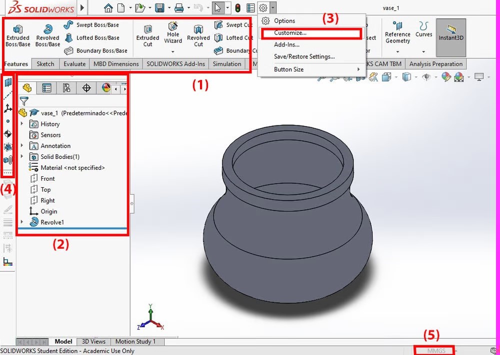
In Figure 1, the area in which you see your actual 3D drawing in is known as the “Viewport”. Above the Viewport, depicted by “(1)” is known as the “Command Manager”. When you are a newbie to SolidWorks the min tabs you will use are “Features” and “Sketch”.
Within Sketch, you will be exposed to various tools that will help you draw 2D shapes. From there you will be able to convert these 2D drawings into 3D drawings using the different tools under the Features tab. The Evolve tab is used for tools such as “Measure”, which displays dimensions within your drawing of the selected surfaces.
Left of the Viewport, depicted by “(2)”, is the “Feature Manager Design Tree”. There are hidden tabs and other menus including a “Property Manager” in the second tab. The “Feature Manager Design Tree” lists all of your created objects and operations inside of your Viewport, including the origin point, planes, cuts and even the material you have assigned to your part.
Above the Command Manager, you will find the usual icons and tools such as “New”, “Save”, “Open” and settings. If you wish to display more menus, you can hover over the “SolidWorks” icon in the top left of the window and a full menu will appear. If you wish to display more icons in your menu, click the arrow on the right of the “Settings” icon and select “Customize”, as depicted by “(3)”. In Figure 1 you will see that the tool “Reference Geometry” “(4)” has been added to the left of the Design Tree.
How to use Solidworks
When creating a part, you will first need to begin by creating a 2D drawing of it, then turn it into a 3D volume by using one of many of SolidWorks’ features.
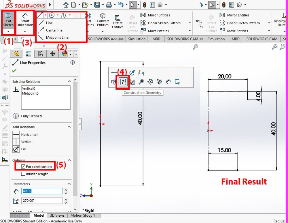
You will start by selecting which “plane” you wish to begin working on. You will find this in the “Feature Manager Design Tree”. Once you have chosen which plane you wish to work on, in the Sketch tab, choose the “Sketch” button “(1)”, this will start your brand-new sketch. When you have completed your sketch, click the same button to “Exit Sketch”.
Creating a line
Begin by creating a line (2). When creating a line, there are 3-line types to choose from:
- Line – This is a normal line, where you first click is where the line will start and when you click for a second time is where the line will end.
- Centerline – This line type helps you to draw your sketch but isn’t considered a solid line or the edge of a sketch (also sometimes referred to as a construction line). Meaning that these lines have no effect or influence on any extruding unless specifically used as a centre line for a revolution.
- Midpoint line – When drawing this line type, you will find that its starting point is its centre point.
Note: If you are starting your drawing with a Midpoint line, the centre of gravity of the part will be at the origin of the drawing. Whereas, if you start the drawing with the normal line the centre of gravity of your part will be above the origin point.
Add dimensions to lines
Next, you will need to add a dimension to your line. To do so you will need to go to the “Smart Dimension” button, depicted by “(3)” in Figure 1. Use this feature to make your line 40mm. This will be the total height of your object.
Change a line to a construction line
You will now need to change the line from “Step 2” into a construction line. This can be done in two ways:
- Choose the line you wish to dimension and leave your mouse hovering over the line. You will soon see a symbol “(4)”, this represents the option to create a construction line if you wish (a construction line is depicted by a dot-dash line).
- Alternatively, you can choose to make the line a construction line by checking the checkbox, ”For Construction” displayed in Figure 1 by “5”.
draw a horizontal line
Now it is required to draw the horizontal lines that will indicate the bottom and the top of the object. For the top measurement, we will dimension to be 20mm, and bottom dimension to be 15mm. Ensure the bottom line is not a construction line. Then draw a short, 4mm line vertically at the end of the top line.
Using 3-point Arcs
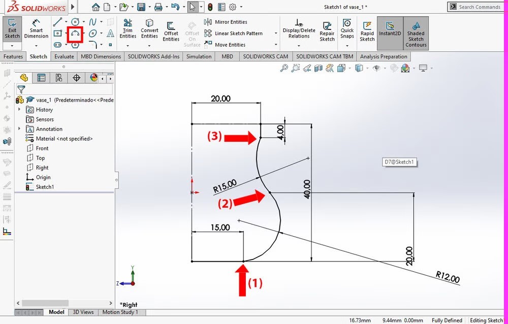
In order to draw a 3-point arc, you will need to click at your start point. You will see that automatically a coincident relation is created. A coincidental relation is when two points are not attached.
Now, select your finish point of the arc and drag your mouse around, this action will change the radius of your arc.
When drawing the arcs, the start point of the bottom arc must have a coincident relation to the bottom line (1). The finishing point must be the same point as the start of the second arc (2). The endpoint of the second arc must have a coincident relation to the 4mm line (3) as seen in Figure 3.
The two arcs explained in “Step 1” must be tangent to each other with no edges. To do this, hold the “Shift” key on your keyboard and select the two curves.
For the last step here, you will need to add dimensions using the Smart Dimension tool. The top arc needs to have a radius of 15mm and the bottom radius to be 12mm. Where the two arcs connect, a height of 20mm is to be assigned.
Finishing Your Sketch Off
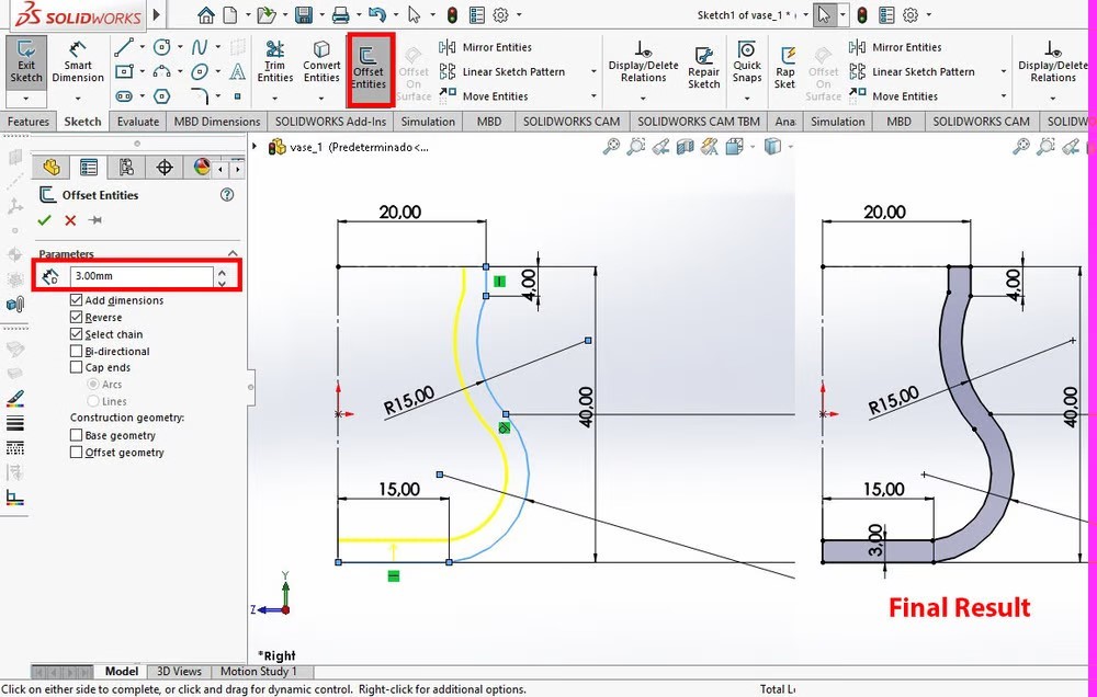
To give the object a thickness is necessary because otherwise, the object will be a complete solid. The obvious way to do this would be to redraw all the lines again from scratch. However, we can be more efficient, by using the tool named “Offset Entities”.
- Start by selecting all lines except the construction line using the Shift button. Now click “Offset Entities”
- Property Manager will pop out on the left and you will need to choose your thickness, in this case, I have used 3mm.
- Ensure the yellow preview points in the correct direction, if not, click the “reverse” key. This will invert the preview and give you the correct offset.
Giving Volume
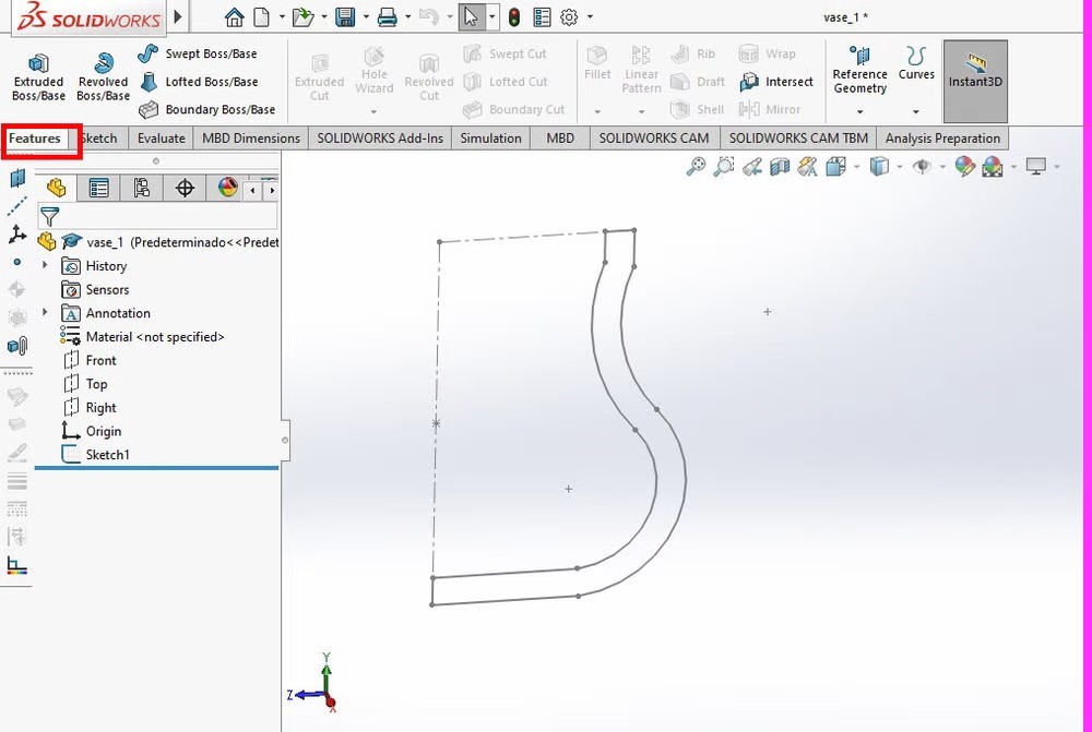
Once you have completed a sketch it is still in its 2D form. There is a multitude of ways to change your sketch into a 3D model. In this example, the “Revolved Boss/Bass” feature will be used. This feature allows the user to revolve an extruded body around a single axis, in our example, this will be the vertical construction line.
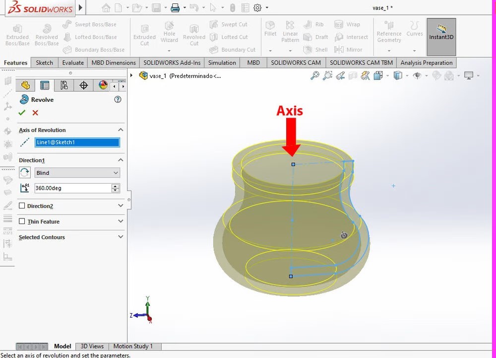
- To make a revolved base, choose the Feature Manager Design Tree
- Click the Revolved Boss/Base and a menu will open on the left. Now choose the line you wish to revolve around
- Click on the line labelled “Axis” as shown in Figure 6, this will create a preview of the finished product
- Once you are happy with the preview you can click the “Okay” tick button
Is Solidworks best for you?
If you have checked how to use solidworks and are not sure whether this software is the best, please refer to this article.
We are pitting different software against each other.
Fusion 360 vs SolidWorks: Leading 3D CAD Software Comparison
AutoCAD vs SolidWorks: Price, Features, Functionality & More
Conclusion
In this article, it can be seen that SolidWorks is an incredibly powerful modelling tool for creating concepts for fun and even how it can be used in the Engineering field. A basic 3D model design for a hollow base has been worked through in a step-by-step layout to display what SolidWorks as a modelling software can perform even though it merely scratches the surface SolidWorks has many incredible features and I encourage anyone who is interested in the software to run through this article and learn how to use SolidWorks and beyond, explore all of SolidWorks’ features and model to your hearts content.