SolidWorks is a world-leading CAD program that offers the user the opportunity to create very specific parts and assemblies depending on your requirements. Throughout your CAD journey while using SolidWorks, no matter how complicated your design or model is, you will always use a particular unit system.
About units used in Solidrowks
In this article, we will discuss how units in SolidWorks can be changed to suit your needs. We will look at the various unit systems that SolidWorks provides and how they can be adjusted for a single document, or even better, a document template for future projects.
Luckily for the users, changing the unit system you wish to use to produce your drawing is easy, you can even change units while modelling or even use a combination of units.
Different types of unit systems available in SolidWorks
While using SolidWorks, you will find the ability to choose from the following unit system:
- MKS – meter, kilogram, second
- CGS – centimetre, gram, second
- MMGS – millimetre, gram second
- IPS – inch, pound, second
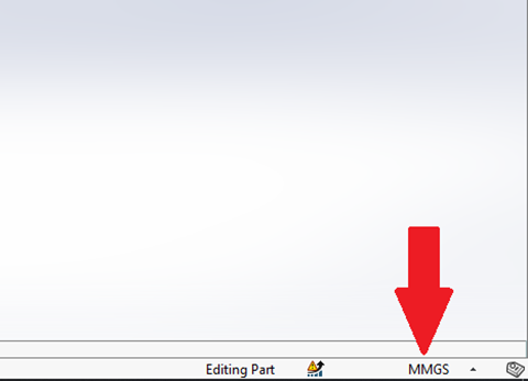
If you are looking to design a part, whole assembly or a simple drawing you will immediately be able to see what unit system you will be using. In figure 1 below, you will be able to deduce what default unit system your SolidWorks has been set up to use by looking at the collection of letters displayed. It will more often than not either be, MMGS or IPS by default.
American customers are more likely to work in Imperial units (technically known as ‘United States customary units) such as inches, feet, pounds and ounces.
As opposed to the rest of the world, which tends to use the Metric system – millimetres, metres, kilograms and grams.
How to change your unit system in SolidWorks
Being able to change the unit system you wish to use can be done whenever you need during your drawing. Simply by selecting the correct abbreviation from the options displayed in Figure 2. When changing units in your drawing, the already existing units will be automatically converted to the new unit system of your choice. Be aware, however, this will convert your dimensions into the new unit system you have selected. For example, a dimension that measures 5 inches will be converted to 127mm; a completely different value but physically still the equal distance.
Mixing up your unit system
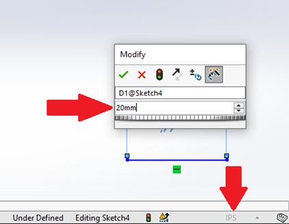
SolidWorks is incredibly intuitive and has a great feature that allows you to choose and change your unit system as you are generating your drawing, even if your drawing is set to a different unit type. An example of this would be if you started your drawing using the imperial system, use the Smart Dimension Tool and convert your dimensions to millimetres by simply typing “mm” as your input value. In doing so this will automatically change the displayed Smart Dimension length into the relative inch length.
It also works in the opposite way. If you begin to work with the metric unit system, if you add an “in” (for inches) to the end of your input value.
Depending on which unit system you choose, within the unit system, you can use large unit types. For instance, when working with millimetres, if you type in “1m” SolidWorks will automatically convert it to 1000mm.
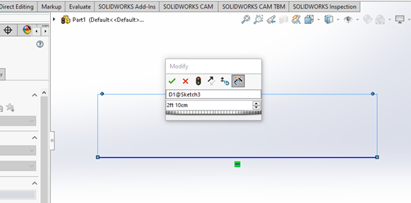
In the imperial system, it is possible to mix the various unit systems. For example, if you type “2ft 10cm” it will convert your dimension to 709.6mm or 27.94 inches.
For information on how to change units in AutoCAD, please refer to the following article:
3 useful features in SolidWorks
We will explain three useful features of SolidWorks.
Fractions in SolidWorks
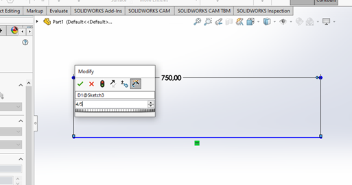
In SolidWorks, you can even use fractions instead of whole numbers which can save you time because you will no longer need to convert your dimensions to whole numbers with decimal places.
You can simply just type using the forward slash symbol on your keyboard. If you wish to type a half, simply type in “1/2” or for a third type “⅓“ and so forth. When typing your dimensions in this manner it will directly convert into a decimal, so “¾” turns to 0.75 and “⅘” becomes 0.8.
Mathematical symbols in SolidWorks
There are so many fantastic features in SolidWorks. Smart Dimensions can make use of mathematical symbols to modify your dimensions. I know this sounds like something difficult to understand, but if you can grasp the idea you can use this method in very clever ways and save you time and money.
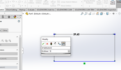
Picture this, you have a part that is 59.6mm in length, you have to increase the size of that dimension by 3 times it’s original length. Normally you might need to grab a calculator for this. However in SolidWorks you can easily type into the Smart Dimension feature, 59.6 * 3 and SolidWorks does the rest. Many other symbols can be used in this manner, you can use the minus, plus, divide symbols or even a combination of the aforementioned.
This allows the user to create elaborate mathematical adjustments with ease and provides confidence to the user, without wasting unnecessary time.
Linking different units in SolidWorks
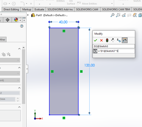
The final useful trick you will learn in this article about SolidWorks is linking dimensions in your sketches. An example of this is if you are required to draw a rectangle which is always to be 3 times higher than it is wide
In order to do this, you need to link the two dimensions. First, draw a rectangle of any size and Smart Dimension the sides. You will now need to choose which value you want to set ss the height. The second value must be linked to the initial value. To do this, start by typing “=” into your Smart Dimension and then selecting the first dimension you Smart Dimensioned. You can now follow this linked unit by typing “*3” after your first input. This will always triple the height of your first dimension, even when the first dimension is changed.
This Method assists you in creating complicated sketches that will update as soon as you make the necessary changes. Allowing you to, save you plenty of time on adjusting values constantly.
Conclusion
Overall, when using SolidWorks you can be assured of using one of the most comprehensive CAD programs available with great usability especially when it comes to changing the units on your drawings. Whether that be upfront to ensure you have uniformity throughout your design or needing to change your unit system during your progress, SolidWorks caters for your needs.