
It’s time to finally resolve one of AutoCAD’s most frequent issues — AutoCAD unit conversion.
If you have ever used the software, you will likely agree that you have more than once needed to look up how to change units in AutoCAD after you started a new project.
In this article, we will look at the various options the software has for handling this frequent situation. The sorts of units and angles will be discussed first, followed by how to express the units in a CAD drawing and then how to change them as needed.
Click here to learn AutoCAD with videos
Units in AutoCAD
While you should consider carefully which unit convention to choose — cm, mm, or inch — the unit of a drawing has no effect on the measured numerical values in that drawing. For example, if you use a dimension to measure a segment of 1000, it means that even if your CAD drawing is set to cm or mm, the measurement value of Dim is still unchanged at 1000.
AutoCAD unit options
The following units can be used when drawing in AutoCAD:
- Inches
- US Survey Feet
- Feet
- Miles
- Nanometers
- Centimeters
- Millimeters
- Meters
- Kilometers
- Yards
- Microinches
- Mils
- Angstroms
- Microns
- Decimeters
- Dekameters
- Hectometers
- Light years
- Gigameters
- Astronomical
- Parsecs
- Unitless
Length Units Overview
We will explain the units of length in detail.
1. Decimal Units
Any unit, such a meter, millimeter, inch, or other, can be used to represent a decimal unit.
Decimal units in AutoCAD don’t refer to any specific unit by name, and the software permits dimensions in the form of units, such as 1.85 or 3.365. A maximum of eight decimal places can be entered in AutoCAD.
- Architectural Units: Feet and inches serve as the foundation for architectural components. The fractional inches are expressed using fractions. It presents feet and inches in decimal and fractional form. For instance, 4′-5 1/2 “. Here, feet are represented by a single apostrophe (‘) and inches are represented by a double apostrophe (“).
- Scientific Units: A measurement yields 1.5500E+01 when the length of 15.5 units is included. Dimensions may be entered in the format of a real number divided by 10, for example, I25E+02. Scientific notation can be used to depict the measurement system. Using scientific notation is mainly beneficial when dealing with extremely large numbers.
- Engineering Units: 1′-3.5 is produced from a measurement that has a length of 15.5 units. Dimensions may be represented in feet, inches, and inch-decimal places. Important to bear in mind is that 12 inches is automatically converted to 1 foot and is displayed as such. To enter the feet, use a single apostrophe (‘). Each engineering unit is equivalent to one inch in AutoCAD’s units. Building plans and topographic maps used in the design and construction of highways and harbors are a few examples of common civil drafting tasks.
- Fractional Units: Fractional units are unitless and display values as fractions rather than decimal numbers, similar to decimal units. A measurement yields 15 ½ units of length, or 15.5 units total. Dimensions may be expressed as a collection of units or as fractional segments of units. The types of fractional units include feet, miles, and inches. The unit of measurement can be represented using fractions.
Angle Units Overview
Various angle measurements can also be specified in a similar way.
1. Decimal Degrees
Decimal degrees measure angles and display them as Real numbers with up to eight decimal places. This form of angle measurement is the default in AutoCAD.
- Radians: The common unit of angular measurement used in different branches of mathematics is the radian, abbreviated as rad. The angle subtended from a circle’s center that intercepts an arc with a length equal to the circle’s radius is defined as a radian.
- Surveyor’s Units: Angle measurement is shown along with quadrant bearings in the form of degrees, minutes, and seconds. In essence, the circle is divided into four quadrants, with the result that no angle can be higher than 90 degrees.
- Grads: The gradian, also known as the gon, grade, or grad, is a unit of measurement for angles used in trigonometry. It is equivalent to one hundredth of a straight angle, or 100 gradians, or 90 degrees.
- Deg/Min/Sec: The format of degrees, minutes, and seconds is used to display angular measurement.
How to Change Units in AutoCAD
Hereafter, this article will show you 3 ways to do it in CAD that only takes a few minutes.
Using the UN Command
The procedure for using UN commands is as follows.
Quick Guide
- Select any point.
- Enter the UN command.
- Press Enter.
- After the Drawing Units tab appears In the Length section, select the Precision section to adjust the unit.
- In the “Units to scale inserted content,” select the appropriate unit for the drawing.
- Select OK to finish.
Detailed Instructions
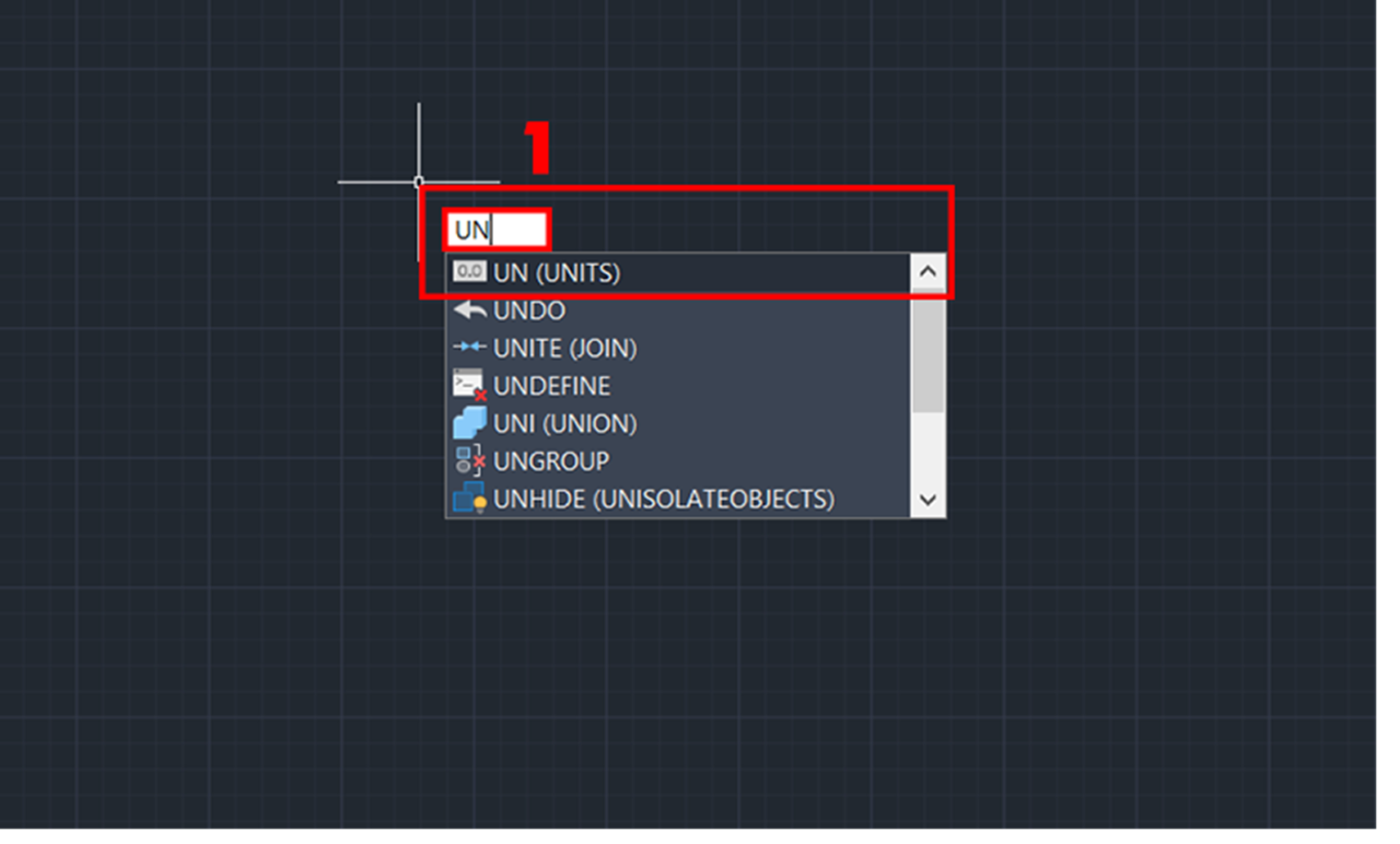
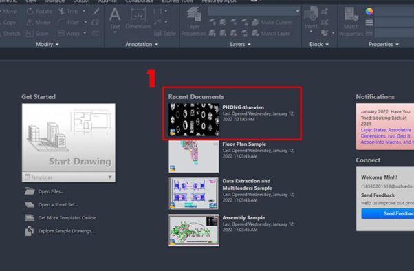
1. After entering the CAD drawing, select any point and enter the UN command, then press Enter.
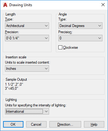
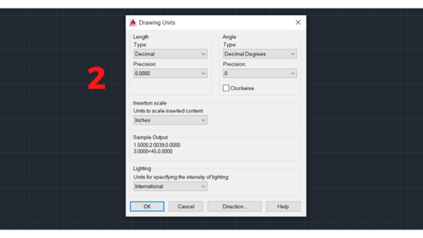
2. After the Drawing Units tab appears, you need to care about items such as Length (Type and Precision), Angle (Type and Precision), and Insertion Scale (Units to scale inserted content).
Length (Type and Precision), Angle (Type and Precision), and Insertion Scale (Units to scale inserted content).
3. In the Precision options of the Length section, you can adjust the unit size, including scientific, decimal (according to TCVN standards, you should choose this option), engineering (for scientists or engineers), architectural, and fractional.
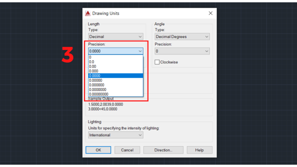
Precision options of the Length section
4. In the Units to scale inserted content section, select the unit that matches the drawing.
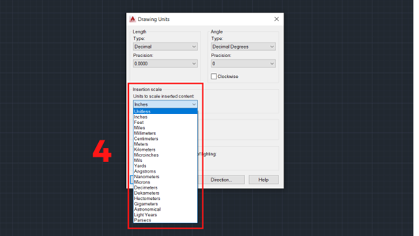
Insertion scale
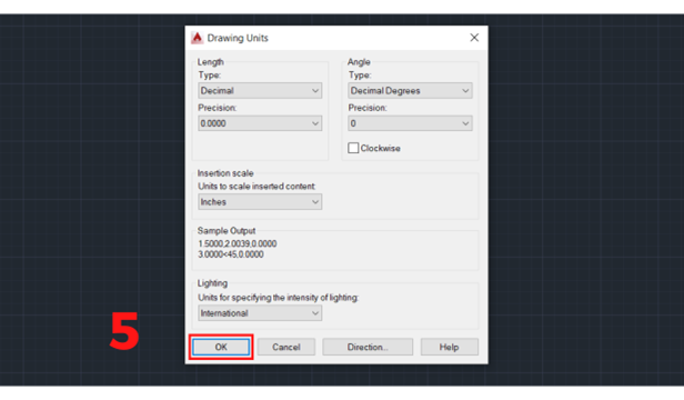
5. After selecting the unit, you need to select OK to complete.
Adjusting Units in AutoCAD by Turning on the Original Template File
The steps to adjust units in AutoCAD are as follows:
Quick Guide
- Select the file you want to adjust the unit of.
- Select New item or press Ctrl + N.
- The Selection tab will appear with 4 sample files.
- Select file.
- Click Open.
Detailed Instructions
1. After entering the CAD drawing, you need to select the file you want to adjust the units for in the interface.
2. Select New item on the toolbar or press Ctrl + N.
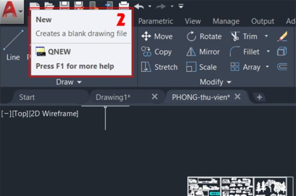
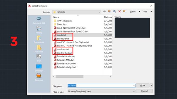
3. A selection tab will appear with sample files. You can select the appropriate template file and click Open. There are 4 sample files that you can choose from:
- acad: 2D sample file in inches.
- acad3D: 3D sample file in inches.
- acadiso: 2D sample file in millimeters.
- acadiso3D: 3D sample file in millimeters.
Installing the File Template
The installation procedure for the file template is as follows.
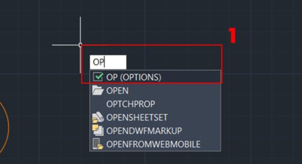
- Select any point.
- Enter OP command (OPTIONS).
- press Enter.
- Select folder Default Template File Name for QNEW.
- Select None.
- Select OK.
Click here to learn AutoCAD with videos
Detailed Instructions
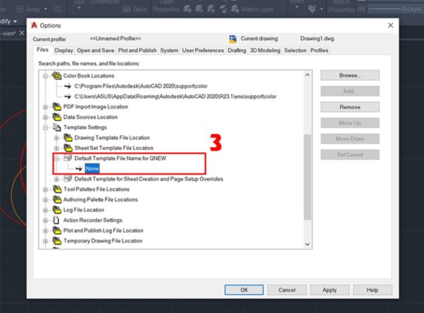
1. After entering the CAD drawing, select any point and enter the OP command (OPTIONS), then press Enter.
2. Select the folder Default Template File Name for QNEW.
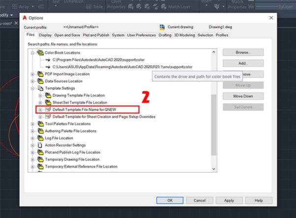
3. Select the item None. As for the other items, you can customize them to suit the version. After selecting, press OK.
For information on how to calculate and set the scale factor in AutoCAD, please refer to the article below.
AutoCAD Unit FAQs
Frequently asked questions about the AutoCAD unit are summarized below.
AutoCAD Online Training Course

There are so many e-learning opportunities and online training courses available it can be so difficult to know where to start. There are courses set up for people who have little to no AutoCAD experience all the way to courses that are suited to people who are very familiar with AutoCAD but need to know about the more advanced features of this highly sophisticated software. Knowing what to choose in order to improve your skills and not waste your money can be difficult with all these options on offer. Sometimes it can feel extremely difficult to choose, especially when you are only just starting your AutoCAD journey. Don’t lose hope just yet.
If you are just starting your AutoCAD journey, and looking for a top-quality beginner’s guide to AutoCAD. Look no further than CADLab’s very own “Beginners AutoCAD Online Course”. This course has been developed over time and designed to cater for people with little to no knowledge of AutoCAD and are looking to get you up to speed and interested in this incredibly comprehensive program.
On this course you will learn to use AutoCAD’s user-friendly interface as well as a whole host of important features within the program. Learning these interfaces and features will ive you an edge in the competitive world we live in today.
Listed below you will find a breakdown of everything you will learn on this course:
- AutoCAD screen operations and initial settings
- Create objects (line segments, circles, arcs, polylines, rectangles, centerlines, etc.)
- Select objects (basic, quick selection, similar selection)
- Using drawing aids (grid and snap, object snap tracking, etc.)
- Editing objects (move, offset, rotate, trim, fillet, stretch, etc.)
- Layers and properties (layer settings, object properties)
- Reusing content (shapes) (block definition, placement, editing, attribute definition)
- Annotative text (text entry, multi-text, editing, styling)
- Annotative dimensions (fills, multileader, edit, style settings)
- Annotative hatches (create, edit)
- Layout usage (page setup, create viewport, control panel)
- Annotative scaling (settings)
- Drawing comparison functions
- Templates (create drawing templates)
- Data management and utilization (external referencing, linking DWG files)
All of these tools are laid out and explained in an easy-to-understand manor and at a pace that is not too fast for you to understand.
Want to know how to apply for the course provided by CADLab? Simply, open the link provided and you will be guided to the webpage that will give you a breakdown of the course and an easy 3 step purchasing method.