Viewports are windows that you can set in AutoCAD to help you view drawings at different scales or to view different parts of an object in 2D or 3D space.
The primary purpose of AutoCAD’s viewports is to simplify the view of the model by splitting a complex drawing into different angles or perspectives, optimising the design process and helping to create highly detailed drawings.
Viewports reduce the need to use zoom and pan tools to search for errors or small details in the drawing, both in Model Space and Layout Space.
Creating a Viewport in Model Space in AutoCAD
It’s far more common to work directly in the Paper Space when using viewports; it’s also possible to insert new viewports from the Model Space. This allows you to select a specific part or section of the drawing and generate a new view. To accomplish this, you need to follow the steps below.
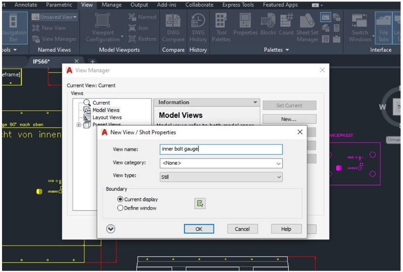
1. Click on the View tab in the Model Space, then click on View Manager located above the Named Views tab. A new window should pop up. Select the “New…” option and click OK.
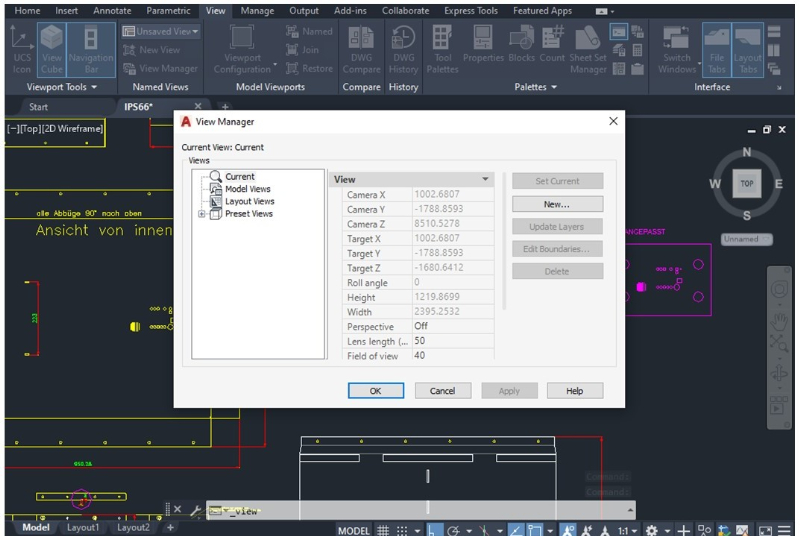
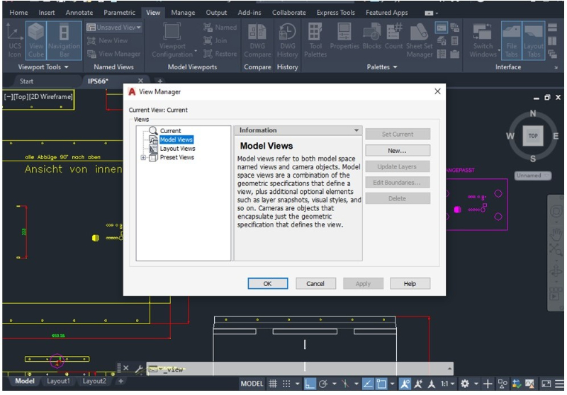
2. Click OK again and make sure the Model Views option is selected (highlighted in blue in the left column).
3. A new window will appear with the New View settings. Type the view name and click on the “Define window” option to select the part of the model you want to convert as a new viewport. Then click OK.
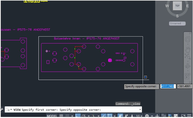
4. Use the mouse to define the extent of the view by enclosing the object or section with a rectangle. Once you complete this step, press Enter. The new view should be created.
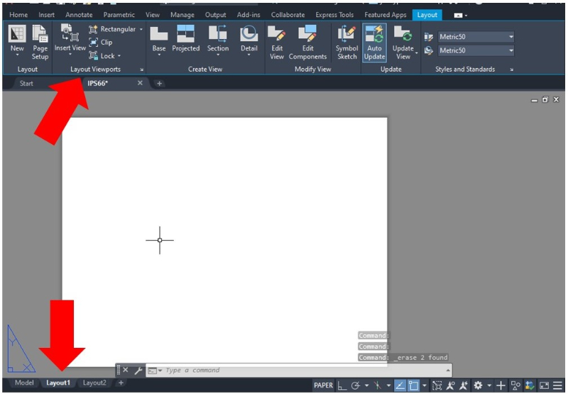
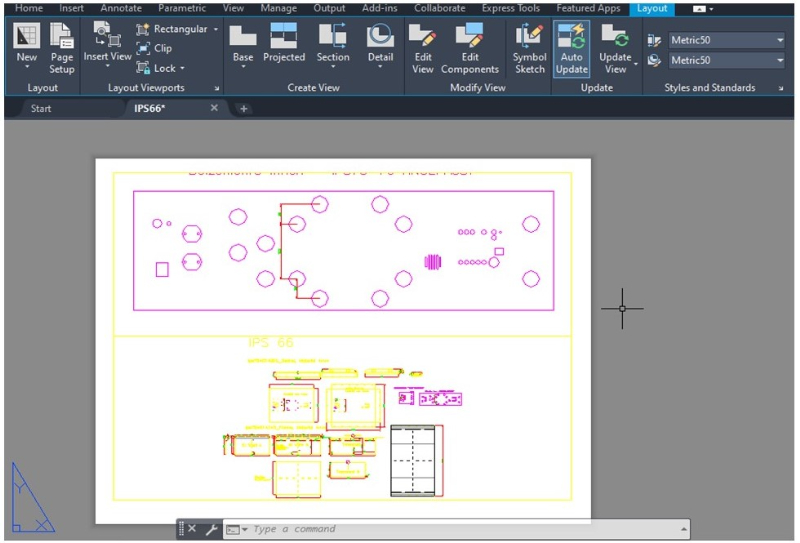
5. Use the mouse to enter the Paper Space by clicking on the Layout1 window at the bottom of the screen. A blank sheet should appear with the Layout tab settings at the top of the screen (as shown in the picture below).
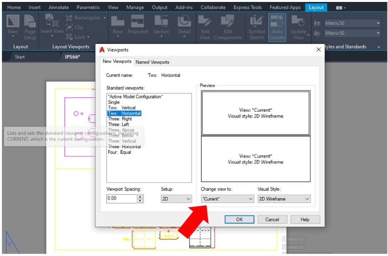
6. Select the Insert View option in the Layout Viewports tab and a new window will appear. You can select the viewport configuration by selecting the option you like in the left column (Single, Two: Horizontal, Three: Right, etc.).
7. Select the viewport section where you want to display the view created in the previous steps by using the Preview window. Once you select the desired option, click the “Change view to” menu and change from Current to the new view name. Then select OK.
8. Use your mouse to draw the viewport shape with the desired measurements by specifying the external points (length and width) enclosing the view. The new viewport should appear on the screen as shown in the picture below.
The basic functions of AutoCAD are described in this article.
What is AutoCAD: Functions and operation guide for 2DCAD beginners
Creating a Viewport with an Object’s Shape in AutoCAD
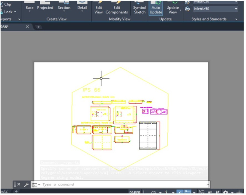
By default, viewports have a rectangular shape. However, you can select a polygon or a custom shape to enclose views.
You can select the Polygon or Object options by clicking the down arrow next to Rectangle in the Layout Viewports tab, which allows you to draw the shape you want.
The main difference between the above options is that Polygon creates polygons by inscribing or circumscribing the vertices inside or outside a circle of the selected diameter, whereas Object allows you to create a shape by drawing a polyline across the empty space.
The images below show a viewport with a hexagonal polygon and a full view of the model inside it.
AutoCAD viewport scaling
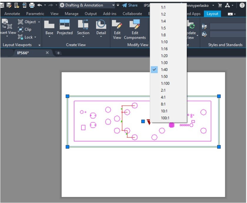
A viewport can use scales to appropriately fit objects within it or to zoom in on a specific part of the drawing. Controlling the viewport scale is very easy. Click the inverse red triangle placed in the centre of the viewport.
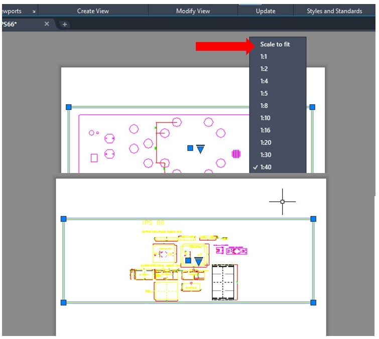
A list of the available scales should appear on the screen. The current scale will be checked and highlighted in blue as shown in the picture below. After selecting the scale you want, the viewport should update.
Sometimes, you might need a specific scale that doesn’t appear in the scale list provided by AutoCAD.
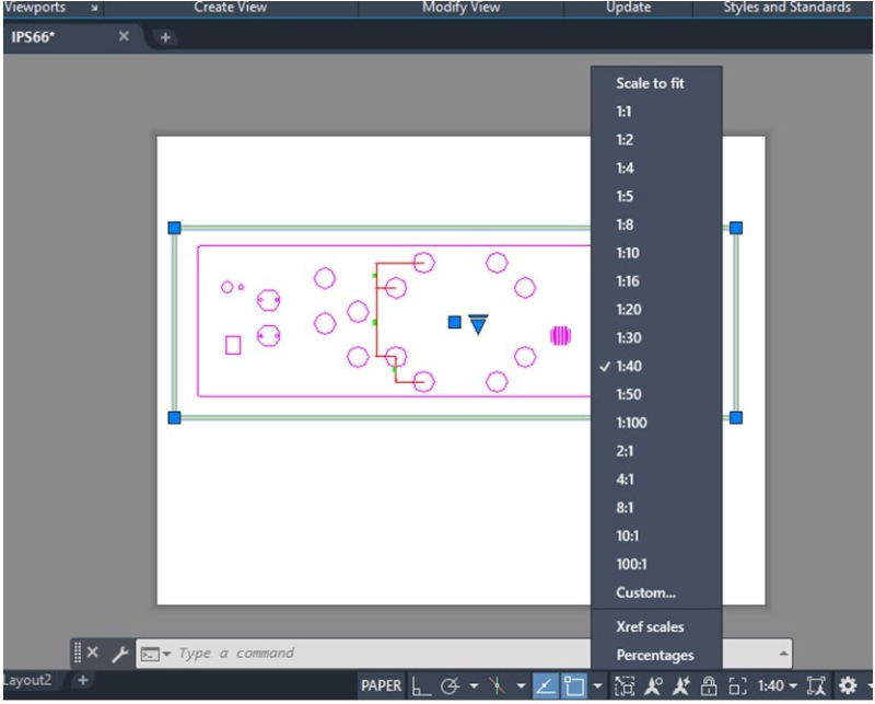
1. To set a custom scale, select the current viewport scale value placed at the bottom of the screen and the scale list will appear again. Then click on “Custom…”. Make sure the viewport is not locked; otherwise, you won’t be able to change the scale
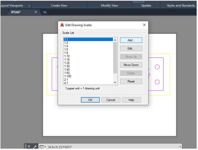
2. A new window will appear with the Edit Drawing Scales settings. Select Add to enter a new scale and click OK.
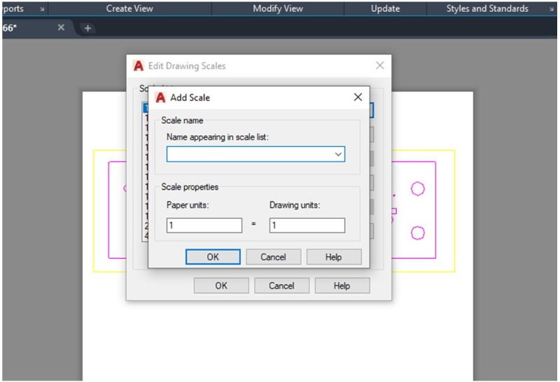
3. Enter a name for the new scale and set the appropriate units. Click OK, enter the new scale (up or down as required) and press OK. The new scale should now appear in the scales list.
4. You can also select “Scale to fit” so the model fits exactly the viewport shape without needing to calculate or guess the appropriate scale.
For more information on techniques related to scale in AutoCAD, see this article.
Moving the Viewport in AutoCAD Layout Space
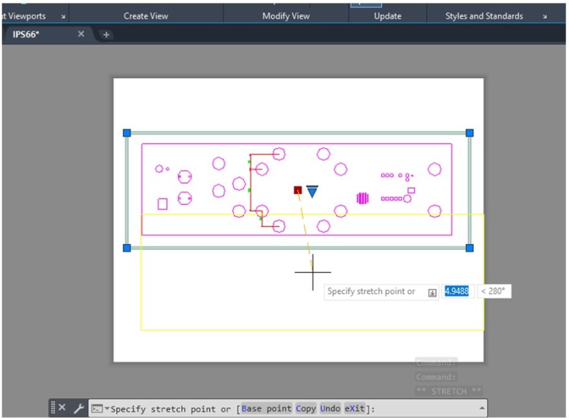
You can move the viewport window across the Layout Space by clicking the blue square located in the centre of the viewport. The square turns red once selected, then you can use the cursor or enter the coordinates to move the centre of the viewport and press Enter.
Annotations and Viewports in AutoCAD
A good option to annotate drawings inside the viewport is creating a new layer for notes or dimensions.
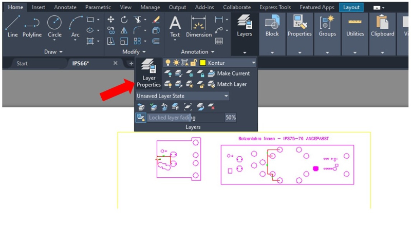
1. Create a new layer by clicking the Layer Properties in the Layers tab as shown in the picture below.
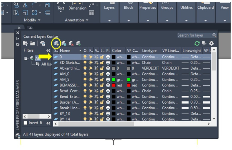
2. After selecting the Layer Properties option, a new window will appear showing Layer settings. Click the New Layer icon (it’s the 1st icon from left to right with the yellow star) to create a new layer for the annotations.
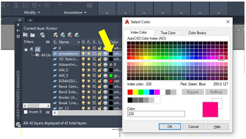
3. Enter a name for the new layer. For our example, the layer is named ‘Annotations’. Click the colour icon associated with the new layer and select a different colour from the current drawing to make the annotations stand out. Then click OK.
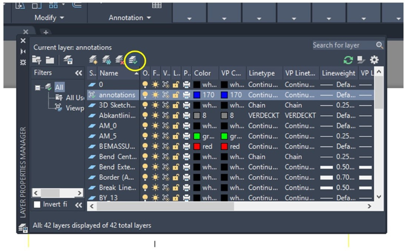
4. Select the new layer and click the “Current layer” icon (it’s the 4th icon from left to right with the green checkmark). You can now close the Layer Properties Manager window.
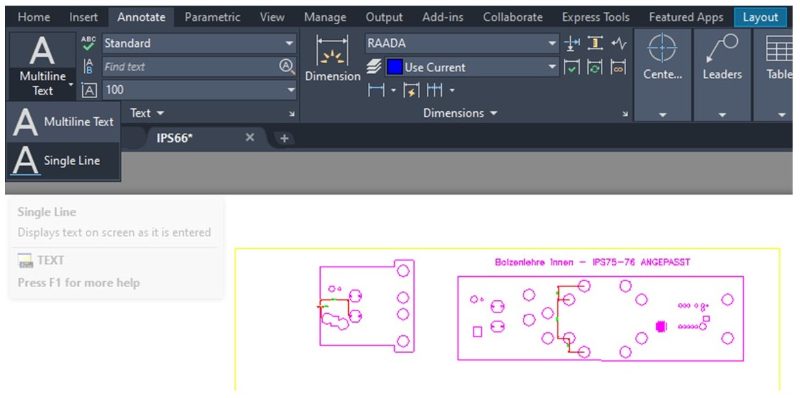
5. Select the Annotate tab and click on the Multiline Text menu. Select the Single Line option as shown in the picture below.
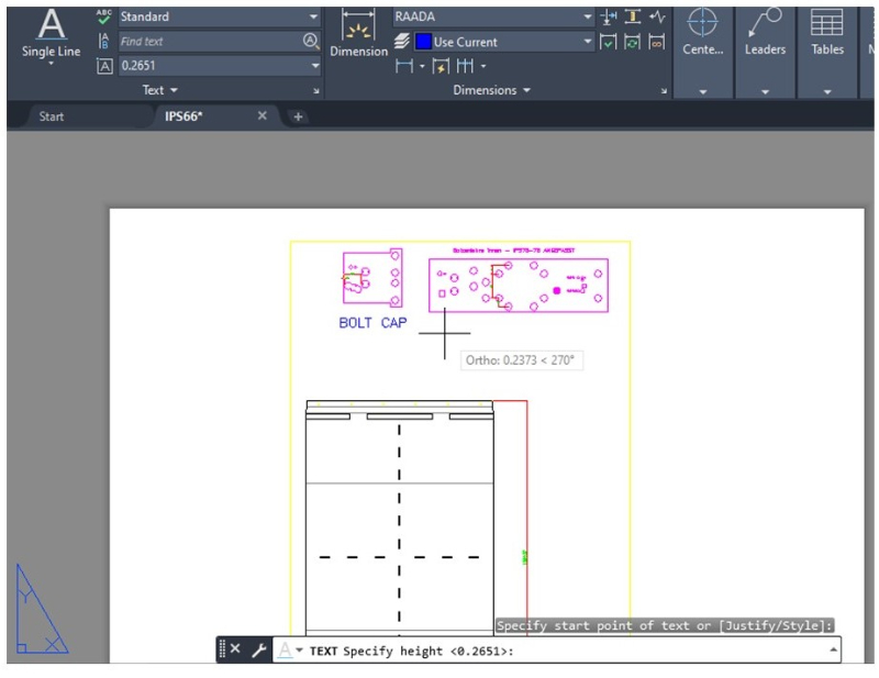
Use the cursor to indicate the annotation’s location and height inside the Paper Space. You can check the font size in the Text tab and the layer colour in the Dimensions tab. Once you have provided the necessary information, AutoCAD will place a tiltable cursor in the Paper Space you have selected so that you can start typing your notes.
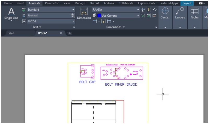
You can stretch or move the annotations in the viewport just as any other object in the Paper Space.
If you want to learn more about CAD techniques, this seminar is a good option.