What is SolidWorks?
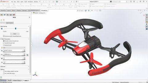
SolidWorks was first released in 1995 as a 3D CAD software program which runs primarily on Windows. In 1997 it was acquired by Dassault Systemes in France, which is best known for its high-end 3D CAD software, “CATIA”. SolidWorks is a 3D CAD software program for machine design, used in various industries such as industrial equipment, medical equipment, architecture and factory design. It has a fast-growing user base, with around 5.6 million users worldwide (as of October 2018).
In addition to basic features such as solid modelling, surface modelling, assembly and drawing creation, it has a broad range of specialty features, including sheet metal, welding and moulding.
User Interface
First of all, I’ll explain the user interface in SolidWorks.
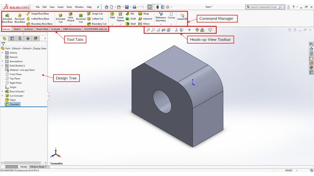
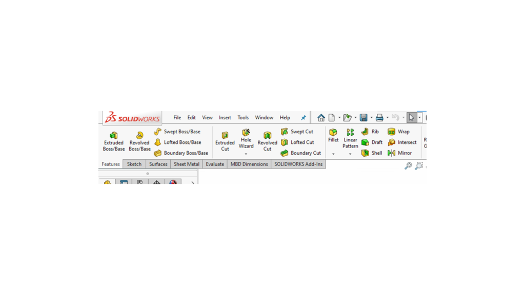
Command Manager
Tool Tabs
We can switch between the Sketch Toolbar, Features Toolbar or Surfaces Toolbar etc. by clicking the tabs.
Heads-up View Toolbar
This toolbar is used for controlling the view .
Design Tree
Sketches and features created are added here as a history.
Mouse driven View commands
[Zoom in/out]
Spin the wheel forward to zoom in and back to zoom out.
[Rotate view]
Hold down the wheel and move the mouse to rotate the view.
[Pan]
Hold down Ctrl and drag with the middle mouse button.
Modelling flow
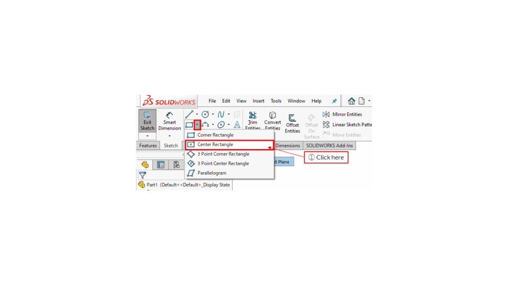
You can create a sketch on a default plane (“Front Plane”, Top Plane” or “Right Plane”) or a created plane. When you select a plane, an icon for creating a sketch is displayed near the mouse. Click the sketch icon to create a sketch on the selected plane.
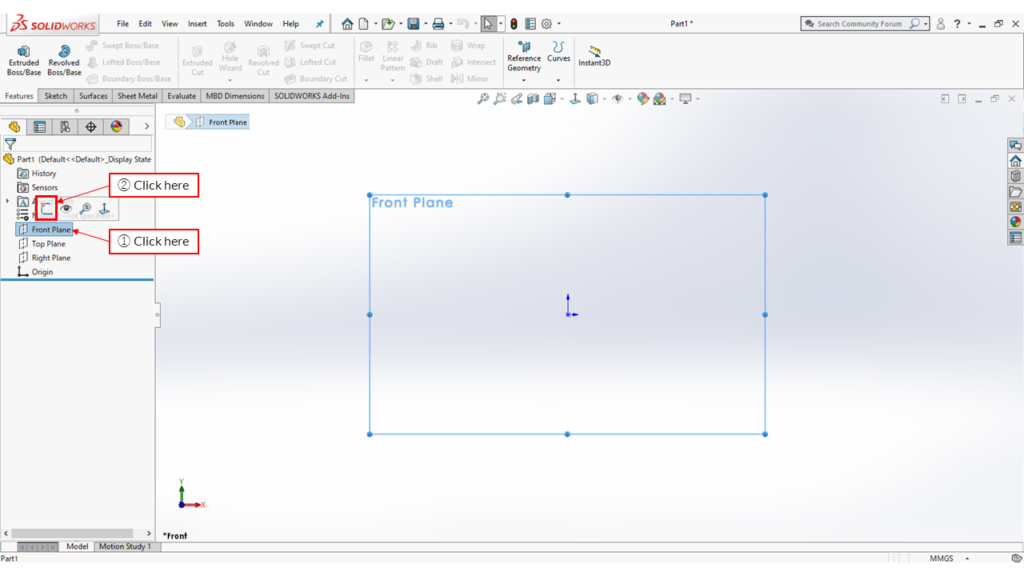
1 – Click here
The Sketch tool tab is selected automatically. We are going to draw a rectangle around the origin, where the red arrows are.
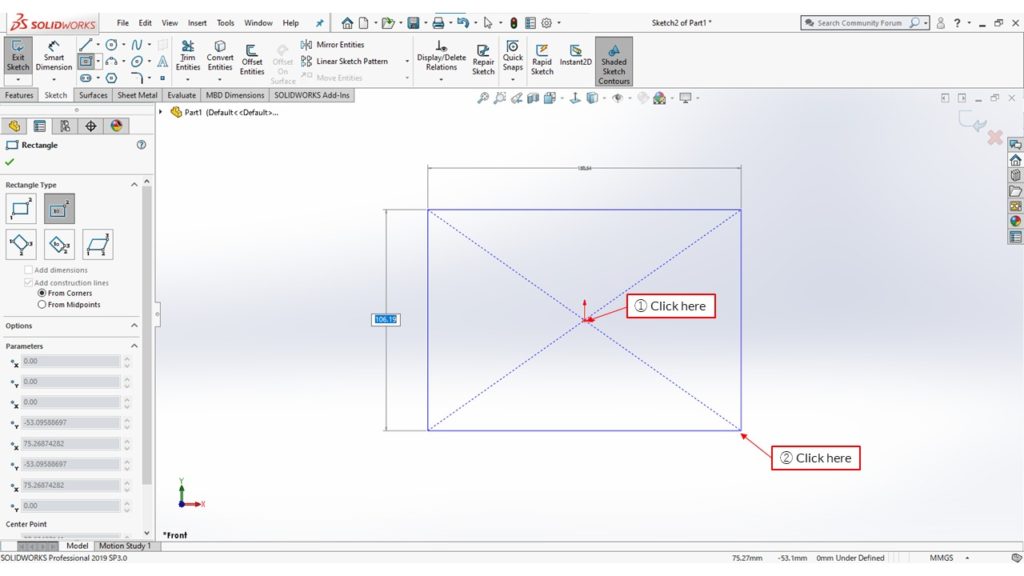
Specify the size of the rectangle. Once fully specified, the sketch lines turn black from blue.
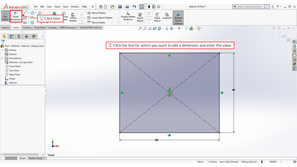
2 – Click the line for which you want to add a dimension and enter the value.
Press Exit to finish the sketch.
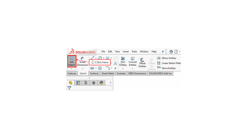
Now we make a 3D model with the created sketch using the [Extruded Boss/Base] in the Features Toolbar.
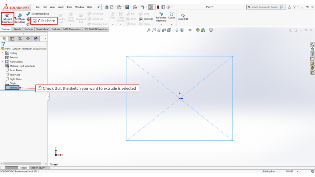
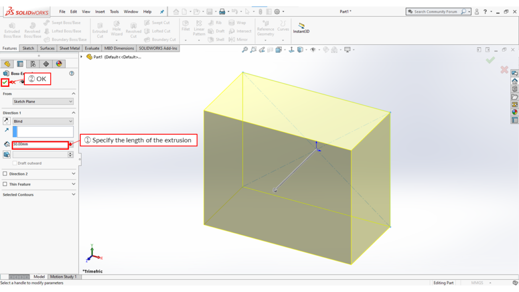
1 – Check that the sketch you want to extrude is selected
1 – Specify the length of the extrusion
The created sketches and features are registered in the Design Tree on the left side. You can edit/delete them by right-clicking.
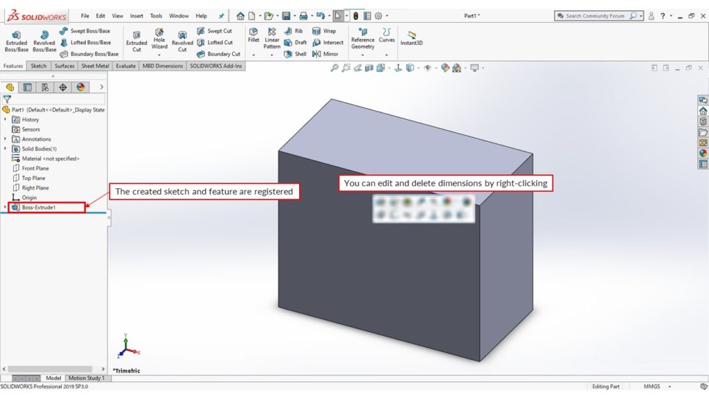
The created sketch and feature are registered.
You can edit and delete dimensions by right-clicking.
Next, we make a circular hole in the block. Select a surface on which to sketch a circle and start sketching.
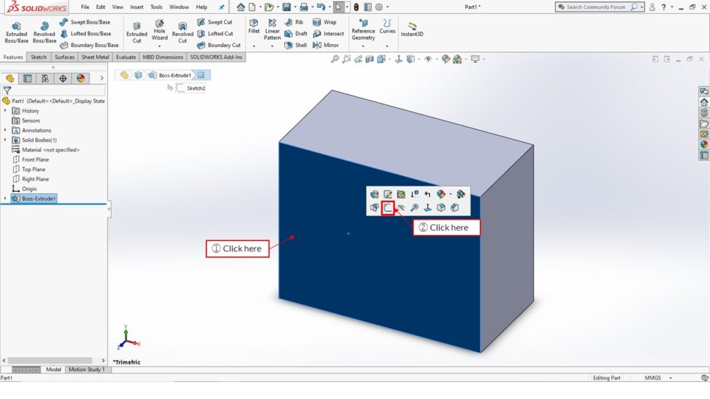
Create a circle in the middle of the rectangle.
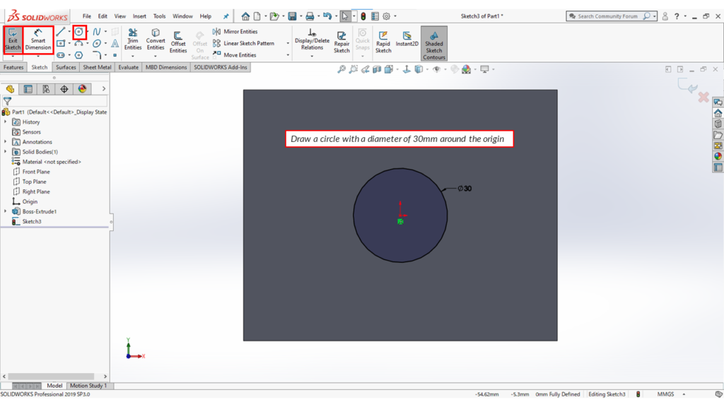
Draw a circle with a diameter of 30mm around the origin.
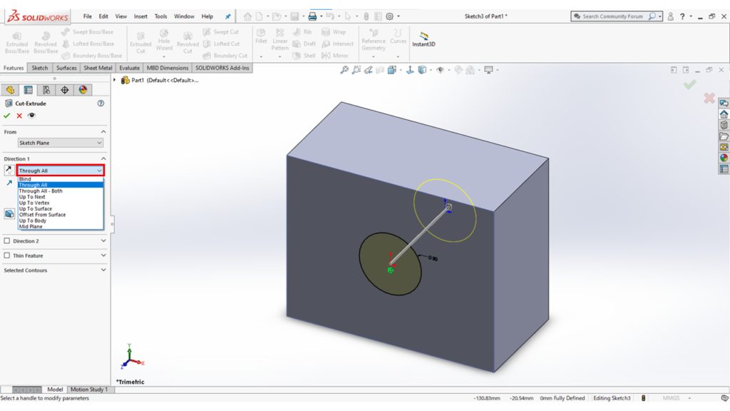
Exit the sketch and click [Extruded Cut]. Select “Through All” to make a through-hole.
Note: This time I used Extruded Cut, but you can also use “Hole Wizard” to create a hole. This enables you to create screw holes, counterbore holes, etc. in SolidWorks.
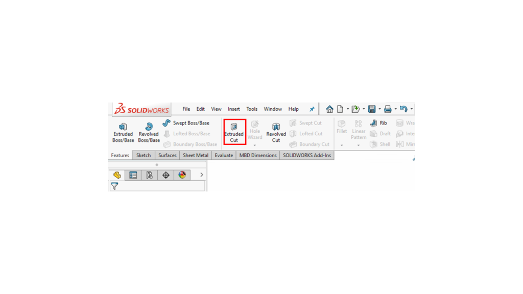
You can also use [Fillets] or [Chamfers] to round or bevel corners.
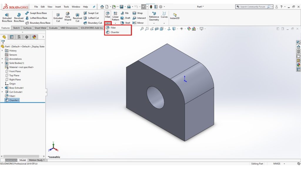
By using the commands shown so far, you can create a complex shape as shown in the diagram below.
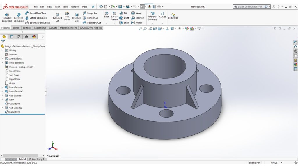
There are also other features such as Revolves, Sweeps and Lofts to create various shapes.
System options
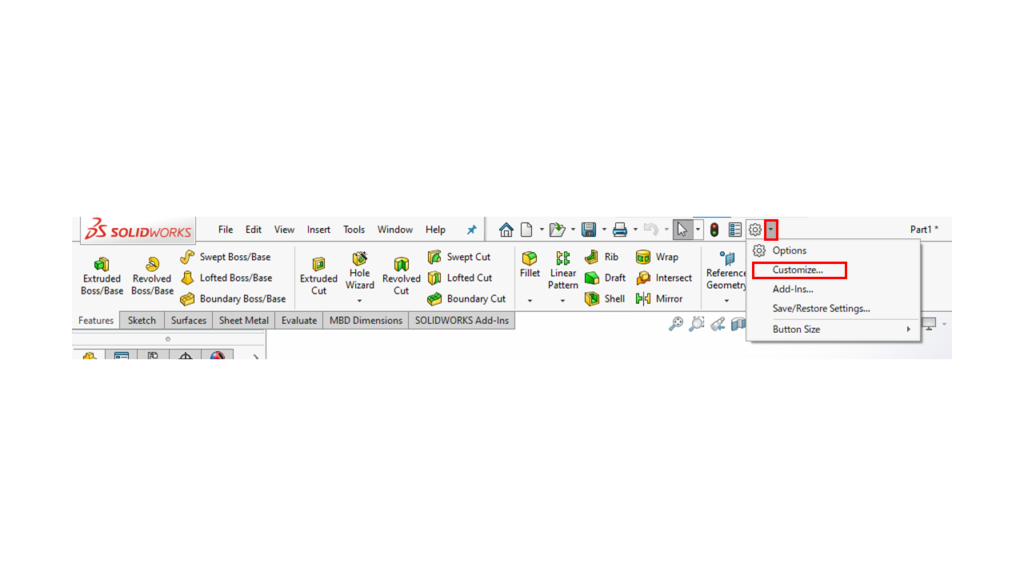
You can specify System options by clicking “Options” (the gear mark) to open the System Options dialogue box in SolidWorks.
The diagrams used to explain the flow above are in the Classic icon colour scheme.
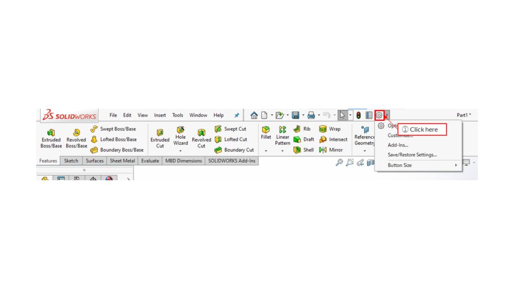
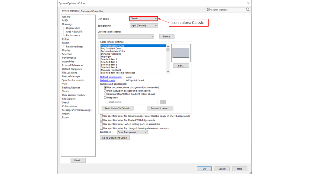
1 – Click
Icon colours: Classic
The image below is in the Default icon color scheme. Which color scheme do you prefer?
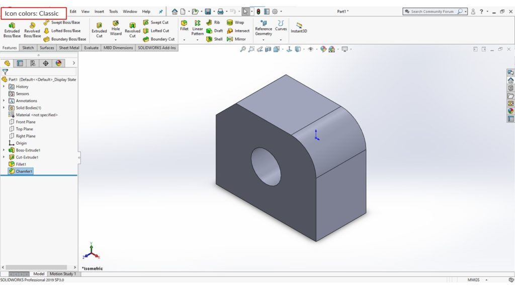
Icon colors: Default
You can set shortcut keys for your convenience and use a Mouse Gesture as a shortcut to execute commands quickly, similar to a keyboard shortcut.
Making good use of shortcuts helps you work more efficiently.
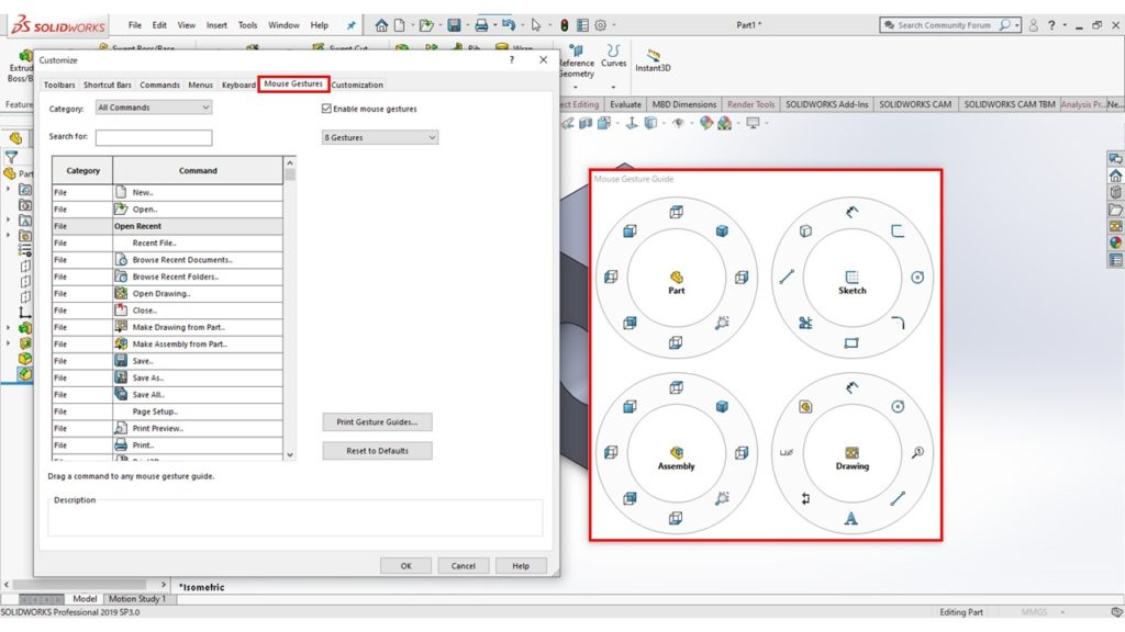
Right-drag
This article is a summary of how to use SolidWorks.
There are many other features, so when you get the chance, look out for them and try using them.

