Isometric drawings play a very significant role in the design industry, whether it be mechanical, architectural, or any other industry where CAD software or hand drawings are used. In our guide below, we cover how to create isometric drawings with the most commonly used CAD software (AutoCAD, SketchUp, SolidWorks, and Fusion 360).
An isometric drawing is a view of a three-dimensional object that displays all the necessary details of its structure without having to move it around to view other sides or requiring multiple views. While the end results are the same across all CAD software, the process to create isometric drawings are different.
How to Make an Isometric Drawing in AutoCAD
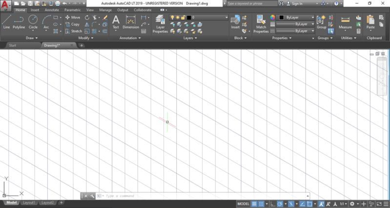
After starting AutoCAD, you need to edit the preferences. For that, Type “+DSettings” in the command line and select the option that appears. A drafting settings
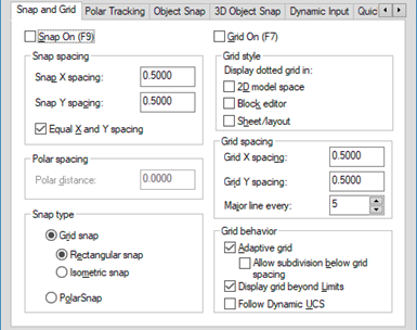
dialog box will appear as shown below. You need to change the snap type from rectangular snap to isometric snap.
After editing the drafting settings, an interface will appear that will look like the screenshot below. On the grid lines, you can snap new lines to draw shapes.
You need dimensions for drawing the isometric view of the part that you want in AutoCAD. And, for that, you need views from at least three sides of the part with the essential dimensions. Using those dimensions, you can draw 2D sketches of the views you have and then use 3D commands to turn those sketches into a three-dimensional model.
We suggest first sketching a view that you feel is easier to create and then extrude it using the extrude command up to the required length, after which the other design commands will follow to complete the required model.
One thing to note is that the isometric environment has either straight vertical or negative 30- or 60-degree lines as grid lines, which is similar to the condition when you use a normal sketching or modeling and annotation environment with horizontal and vertical grid lines. You shouldn’t have much of a problem getting most of the lines to be in accurate orientation for the isometric view, because the directional snap of the lines you draw will be in the orientation of the grid lines.
This only works if you have orthogonal snap turned on in the isometric snap environment. If you want easier designing, first draw the basic lines that need to be drawn in the vertical and iso directions, and then turn the orthogonal snap off, which enables you to draw the remaining geometries to complete the drawing.
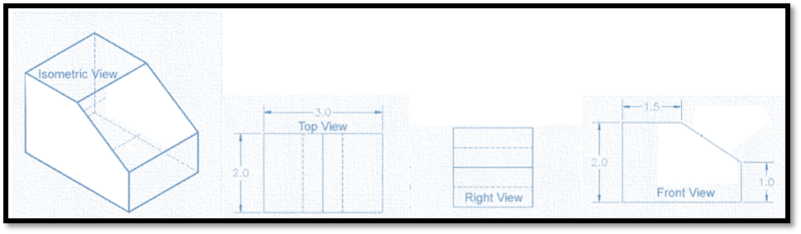
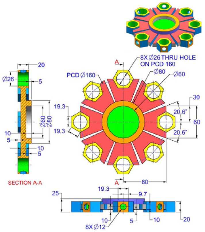
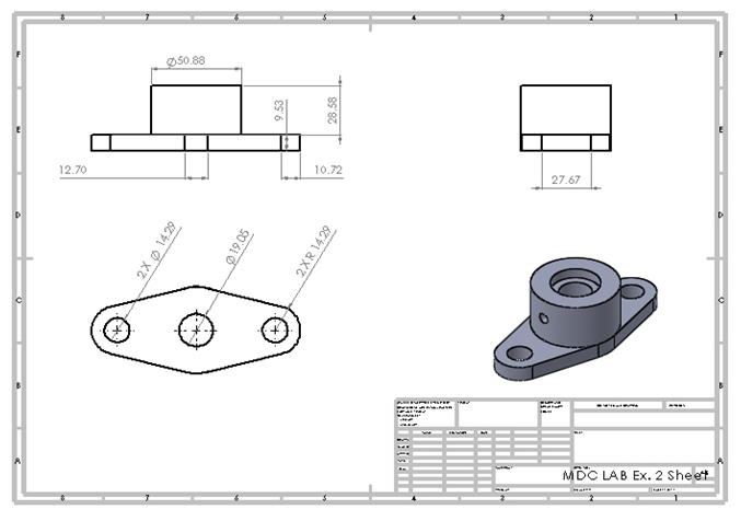
Here is an example of an isometric drawing of a part drawn from three of its views.
How to Make an Isometric Drawing in SketchUp
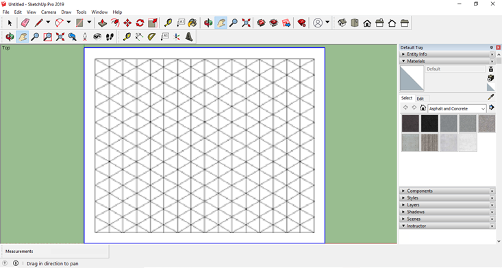
SketchUp is another two- and three-dimensional design software. It is mostly used by architects and 3D designers. With this software, you are able to use files from other software like AutoCAD, and also make isometric drawings. To draw isometric objects in SketchUp, start by adding an isometric grid.
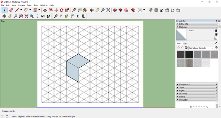
To create an isometric drawing of a cube in SketchUp, first draw the front view of the cube by marking a straight vertical line, then a diagonal line, and then forming a parallelogram to complete the face.
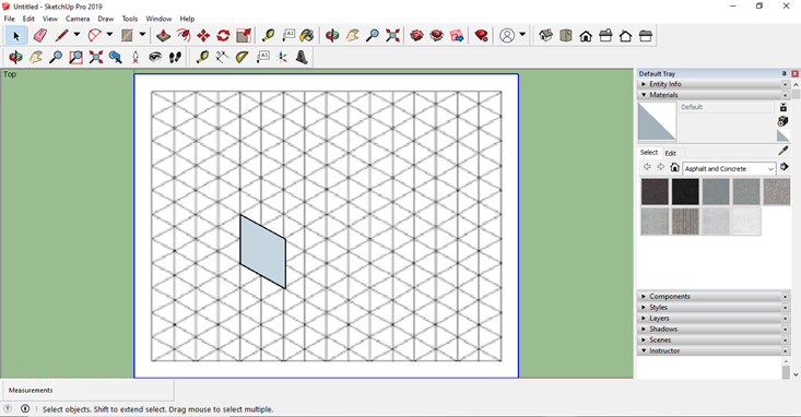
After that, draw the top face of the cube by drawing a parallelogram, as before, on the grid.
Finally, draw a vertical line downward from the free corner of the top face and join its end with a diagonal line with the bottom free corner of the front face.
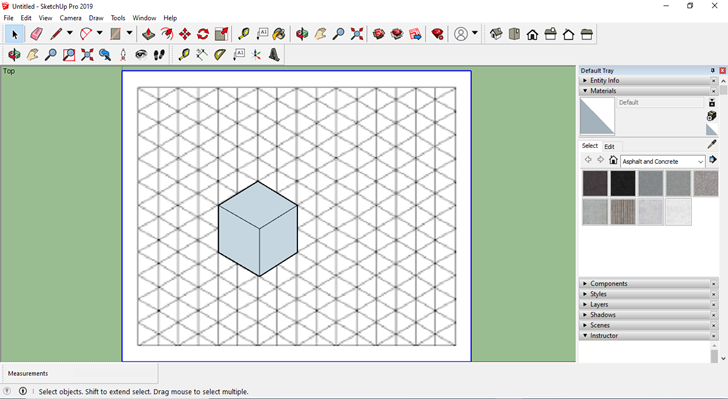
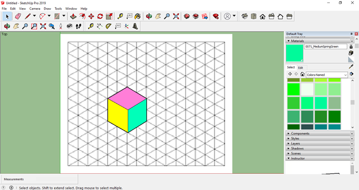
In SketchUp, you can easily edit the color of the sides with the materials tool. As shown in the screenshot below, a cube is completed in isometric view.
How to Make an Isometric Drawing in SolidWorks
SolidWorks is one of the most commonly used CAD software worldwide, following AutoCAD.
It is essentially a three-dimensional modeling software that utilizes sketching in two dimensions. In order to draw an isometric view, you can learn how to use the software to draw a three-dimensional part and simply put that part into isometric view.
You can also get a two-dimension isometric drawing of the part by clicking the “new” icon and then selecting “drawing.” After that, you need to open the file of the part in the command manager and drag its isometric view onto the sheet. You can get the isometric view from a front view or any other view by simply hovering over it or clicking it and then moving your cursor diagonally in any direction you want so that you get the preferred isometric view of the object.
How to Make an Isometric Drawing in Fusion 360
Isometric drawing in Fusion 360 is the same as SolidWorks. You need to draw a three-dimensional part using the software’s available tools and then enter into isometric orientation to get the required view. You can also get the isometric view by opening the part file and dragging and clicking for projected views or selecting from the view selection pane.
Fusion 360 vs SolidWorks: Leading 3D CAD Software Comparison
Drawing Isometric Views in other CAD Software
Through the examples above, we have covered two different methods for creating isometric drawings, and there are many other CAD software available that utilize either of these methods. With that being said, the end result should be the same, whichever software you use.
How Are Isometric Drawings Used?
Isometric drawings are used in a variety of applications, including:
- Providing a proper display/understanding of an object
- Presenting 3D parts of machines
- Taking measurements of objects
- Displaying the various parts of a building and perspectives
- Enhancing an artist’s designs and sketches
- Making infographics
The Importance of Isometric Drawings
With an isometric drawing, single color drawings can be made and multiple color schemes can be used to properly communicate the design. Some artists, architects, and engineers use freehand drawings in isometric projection to put their design concepts and immediate thoughts on paper in less time, allowing for greater work efficiency. This helps them work quickly in the early phases of the design and modeling process, thus analyzing multiple ideas at once without the need for complex sketches and projections of objects. Isometric drawings help designers and architects show the 3D details of the project early to clients, which helps in decision-making for the selection of specific designs.
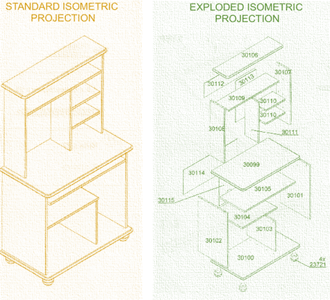
In isometric drawing, designers can use multiple views of an object. For example, to show the interior details of objects, designers can utilize exploded views. This helps in more easily showing the integration and harmony of small parts and components in the objects and their relative role in the object or machine.
Architects may use the exploded view to show the interior design of a house or apartment. The exploded view can help to show the structural details and material displayed inside the walls of the building. Structural engineers can use this method to communicate the design features of complex structures like bridges. Industrial designers can use an exploded view to show the details and dimensions of interior components and thus better assist in more effective communication between the design and manufacturing teams.
In the illustration below, an isometric drawing of a building is shown. Various parts and three-dimensional details are displayed in this image. Isometric drawing can help architects properly communicate their designs to clients.
In another illustration below, you can see that an isometric drawing of a building is given. In this isometric drawing, the rooms and walls with doors and windows are shown. This drawing helps in understanding the space and its usage more effectively than a two-dimensional drawing, which only shows the layout from a top view. This drawing displays the details of the walls as well giving a complete view of the building.
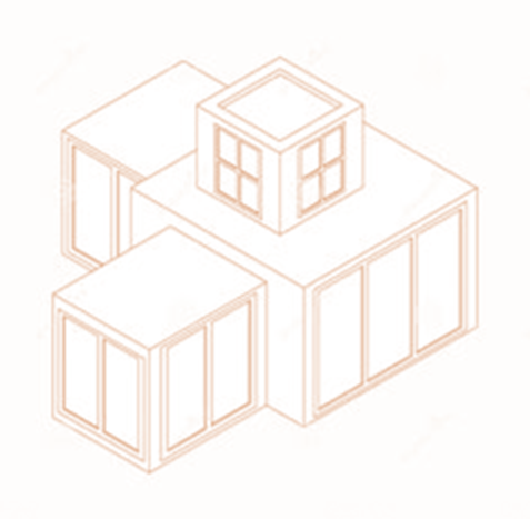
In the image given below, you can see that an isometric drawing of a building is given.
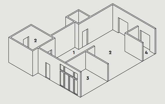
In this isometric drawing, the rooms and walls with doors and windows are shown. This drawing helps in understanding the space and its usage more effectively than only a two-dimensional drawing which only shows the layout from a top view. This drawing helps in displaying the details of the walls as well thus can give a complete view of the building. And so, it makes the design process work smoothly.
Add Isometric Drawings to your Production Pipeline
Whether you are a veteran designer or are new to CAD, learning to quickly create isometric drawings gives you the opportunity for improving efficiency and better communication with your project’s decision makers. While each CAD software varies in its method for creating isometric drawings, the end results are the same and only take a little bit of practice to become proficient. We hope this article helps you become a better CAD designer or engineer, so that you can continue to prosper in your industry.