If you’re new to AutoCAD, this free online guide covers everything you need to get started on your first project. From basic terminology and concepts to creating and modifying 2D and 3D objects, the foundations of AutoCAD are ready for you below!
Click here to learn AutoCAD with videos
What Is AutoCAD?
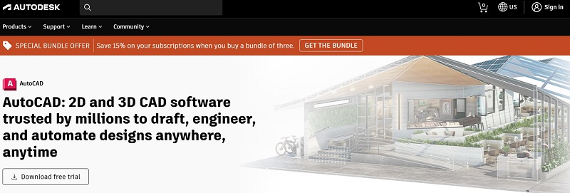
AutoCAD is a CAD (computer-aided design) software developed to draft and draw 2D and 3D models through graphic controllers and commands. This program aids designers, architects, engineers, and construction professionals in generating high-quality virtual models and drawings, optimizing the design process.
It’s owned by the industry-leading software company Autodesk, which currently offers a variety of tools for designers across different fields.
Basic Terminology and Concepts of AutoCAD
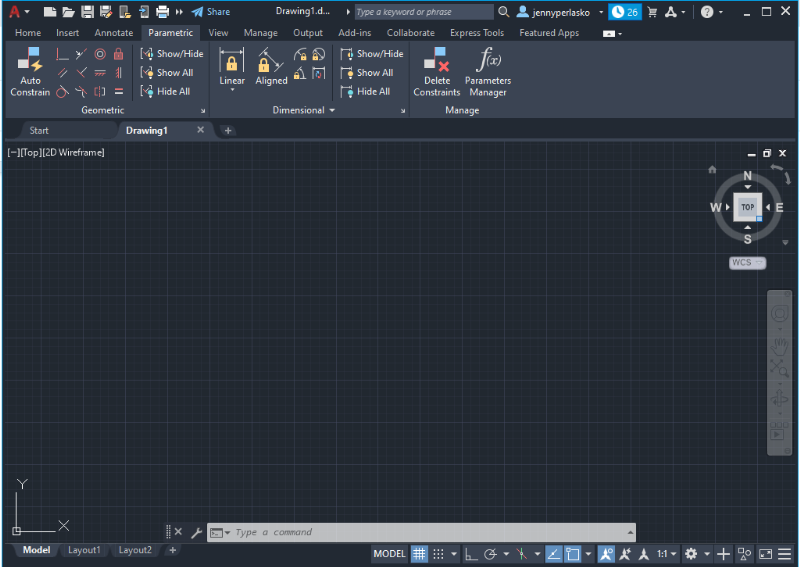
AutoCAD User Interface
Once you have opened AutoCAD, it’s time to create a new project. Depending on the computer’s capacity, initiating the program could take a few minutes.
To start a new project, click on “New” in the left side panel, and the program will show its main working space where the design process takes place. This new space contains a set of basic tools and features to start designing.
Quick Access Toolbar
The Quick Access Toolbar contains all the basic icons, such as opening, creating, and saving files. It’s easy to manipulate and it can be customized.
Ribbon
The Ribbon contains a variety of tools arranged in tabs, to create a more compact interface.
Command Bar
The Command Bar is a search tool for users to find commands by typing them manually. It lists commands and offers information about each with additional tips.
Setting the Workspace
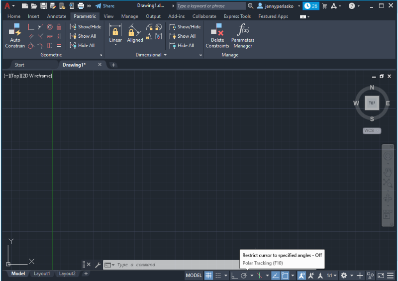
ViewCube
ViewCube is located in the top-right corner and is set to Top View by default. You can change the view to different angles by hovering your cursor over the icon. You will see a coordinate system in the middle of the drawing space where you click on faces, edges, or corners to select the desired view.
Navigation Orbit
Navigation Orbit is a tool to control the display of a view like the ViewCube. It has a round shape and contains cardinal directions to help you with the orientation of the drawing. It also allows you to orbit the drawing space or sketch in a three-dimensional space.
Quick Access Toolbar
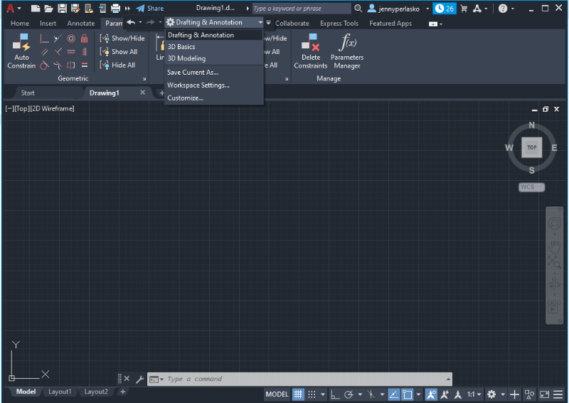
Quick Access Toolbar is located at the top next to the AutoCAD symbol. You can click on the downward extend arrow to customize it. A drop-down menu will appear with many options. One useful tool to add is the Layer icon or the Workspace option to change from Drafting and Annotation to a 3D Modeling environment.
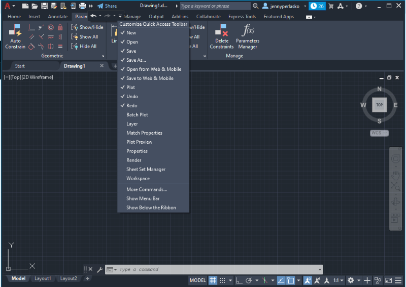
By default, the Workspace in the program will show the option “Drafting & Annotation,” but you can change it for 3D options if they are needed before you start designing.
Setting Units
Type the word “Units” in the blank space located in the Command Bar at the bottom on the screen. You will see that the Units option and a brief description of the command will pop up as you start typing.
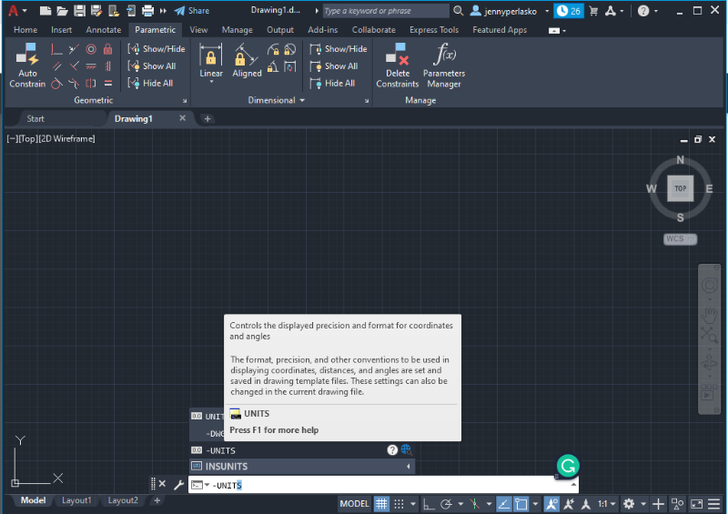
The units you choose won’t affect the creation of objects or the precision of the drawing, but they will affect the length, angles, coordinates, and distances displayed.
If you plan to work with inches and feet, it’s advisable to use the Architecture option (Option 4). If you want to use the metric system, you can choose Decimal (Option 2). You can also specify the format i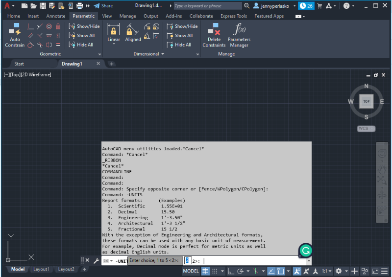 n which the dimensions will appear and their precision (the number of decimals displayed). AutoCAD will ask for all this information automatically, and make you use the blank space to type in the required number of decimals and format. Click Enter upon finishing the units setting process.
Coordinate Systems
Cartesian Coordinates
Cartesian Coordinates is the default setting in AutoCAD, where conventionally, the X represents the horizontal axis moving positively to the right and negatively to the left. While Y represents the vertical axis moving positively when going up and negatively going down.
Polar Coordinates
Polar Coordinates is an optional setting that employs angles and radial distances to represent directions and dimensions in the working space. By convention, the angle is measured counterclockwise from the x-axis and is represented by AutoCAD with the following rules:
- “R” is equal to the radial distance
- “<” is the “less than” sign (represents the angle)
- “Degrees” is the value of the angle in degrees
Modes
AutoCAD allows setting different coordinate modes to restrict how designers create objects and move across the workspace: Orthogonal (Ortho) or Polar mode. These options are located at the bottom of the screen below the Command Bar.
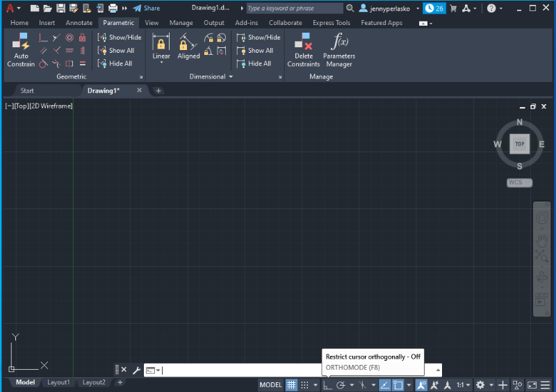
Ortho Mode
Ortho Mode is used to restrict cursor movement to only the vertical and horizontal directions, relative to the User Coordinate System (UCS). It can be quickly set with command F8.
Polar Mode
Polar Mode (or Polar Tracking mode) restricts the cursor movement to certain angles followed by their alignment paths. It can be quickly set with command F10.
Basic Figures in 2D
The following explains how to draw lines and create shapes (squares, rectangles, circles, and polylines) using coordinates.
Creating Lines
There are two main options for creating lines in AutoCAD.
1. Select the Home tab in the top bar and click on the desired line (Polyline, Line, Arc) displayed in the Draw icons.
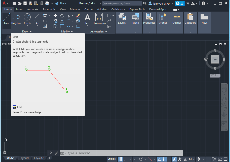
2. Type in the word “Line” in the Command bar at the bottom of the screen and click on the displayed menu option Line.
In both cases, the software will provide a dialog box at the bottom of the screen indicating the next possible steps in the design process. The operation of drawing lines will stop only by selecting “Undo” or using the ESC shortcut key.
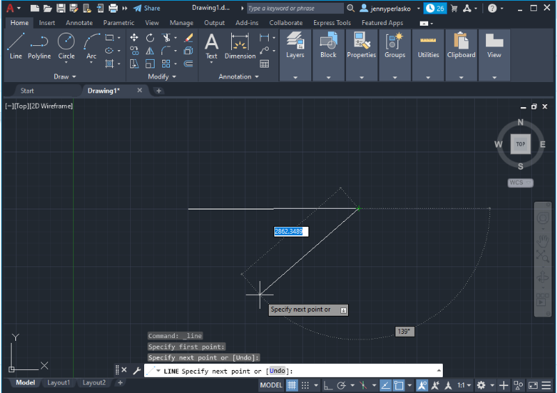
Once you have entered the line command, the program will ask for the first point of the line. You can either click a random point in the drawing space or enter the coordinates manually. Enter 0 for the X-coordinate, and then press the tab to switch to the Y-coordinate, and enter 0 there as well. Press Enter to confirm. This way you will be selecting the CenterPoint (0,0) or origin to start your sketch.
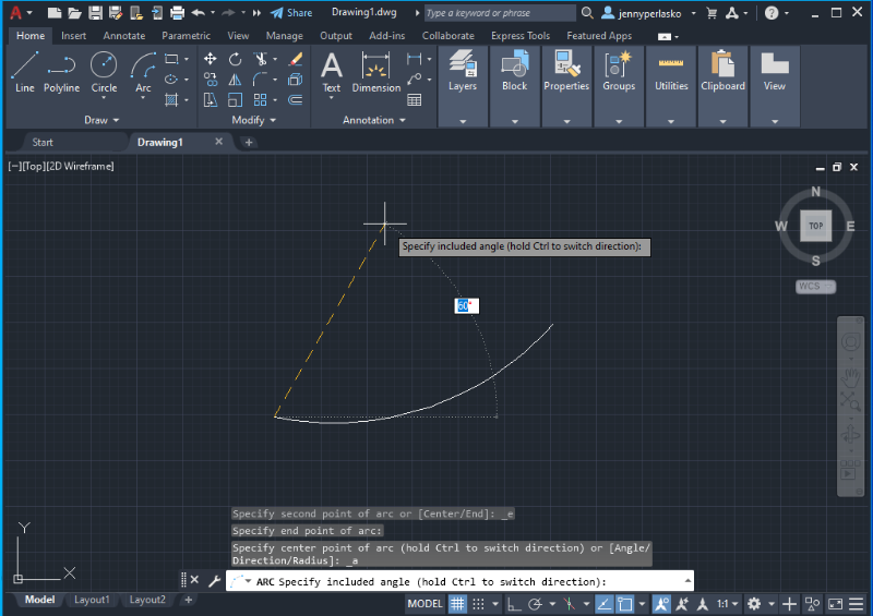
Arcs
Creating arcs is similar to creating straight lines, and the program provides a wide range of options for constructing the arc: Three Points, Start-Center-End, Start-Center-Angle, etc. The option you choose will depend on the information you have available when sketching (dimensions, angles, or radius).
- Depending on the type of arc you choose, the program will ask you to type in the coordinates of the starting point or select it with the cursor.
- It will ask you for the length of the arc, its angle, the ending point, or the length.
- Press Enter after submitting the required information, and follow the instructions displayed on the screen to complete the arc.
Shapes
Using the top bar, you can easily start drawing any shape or line by clicking the drop-down menu next to the Rectangle shape. You can select the type of shape you want: Rectangle or Polygon.
Rectangles
1. If you choose the rectangle, the program will first ask you to specify or type in the location of the first point for the rectangle, as shown in the picture below.
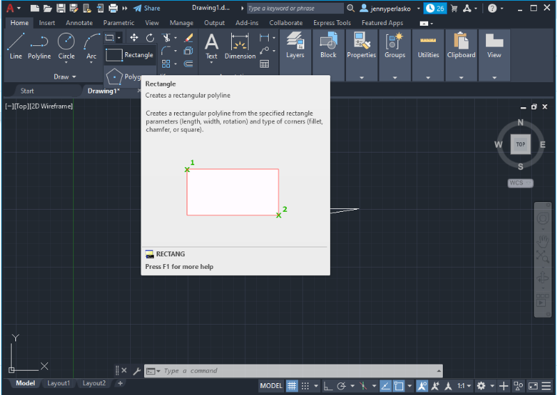
2. Follow the instructions to indicate the next coordinate for the second point (to provide the length and width of the object).
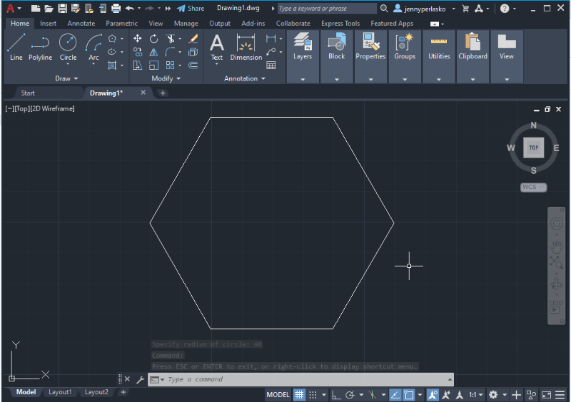
Polygons
- If you choose to create a polygon, the program will first ask you to enter the number of sides of the polygon (starting with 4 as a default value). After filling in this information, press Enter.
- Specify the center of the polygon or its coordinates and press Enter.
- Choose between the options: “Inscribed in circle” and “Circumscribed in circle.” Press Enter after selecting the desired option and enter the circle radius in which the polygon will be circumscribed or inscribed. Users often choose the inscribed option set by default.
You can also use the shortcut key to insert a polygon or use the command bar at the bottom of the screen and follow the same instructions to provide the dimensions.
Click here to learn AutoCAD with videos
Modifying Commands in 2D
There are hundreds of commands available in AutoCAD that designers use to edit, modify, create, and view their models. Experience and training allows you to become comfortable with commands and use them effectively when drawing and sketching. Below, you will find the classification of basic operations according to their functions: modify operations, assembly operations, and operations in 3D space.
Modify Operations
The Modify tab in the top bar contains a set of icons that represent basic operations to help you manipulate, modify, and edit sketches in the workspace. These tools include trimming, mirroring, scaling, moving, exploding, erasing, rotating, copying, and stretching objects. All of them come in handy for designers and can be used both in two-dimensional and three-dimensional space. Here are some guidelines for using some of the most important modification tools.
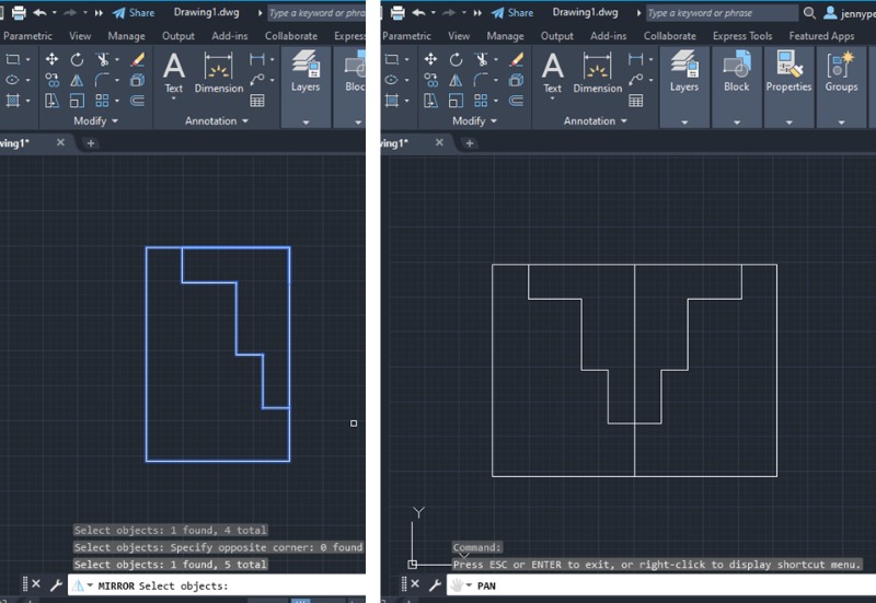
Mirror
The Mirror operation creates a mirrored copy of an object across a specific line to create another half. The Mirror icon is located in the top bar and can be found in the bottom command bar as well.
- After clicking the Mirror option, select the entire object you want to mirror, making sure that all the lines are highlighted in blue.
- The program will ask you to locate the position for mirroring the object. If you want the objects to be joined (as they were a unit), click on a corner that belongs to the boundaries of the object. This point will become the centerline of symmetry of the mirrored object.
- Press Enter after locating the mirroring position, and a mirrored copy of the object will appear on the screen. Use the mouse to rotate or move this new object across the workspace.
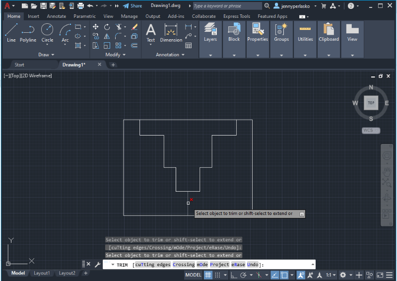
Trim
The Trim operation allows the trimming of objects, lines, and shapes that you select. It can trim individual objects, or select multiple objects by dragging the cursor or “shift + select” all the objects needed.
Once the objects are selected, click the Trim icon located in the top bar or type the word “Trim” in the command bar at the bottom of the screen.
This operation is similar to Erase and both operations are located next to each other. The difference lies in that the Erase command deletes the element chosen from the drawing without taking into consideration the edges and geometry of the drawing. However, it can be used interchangeably depending on the case.
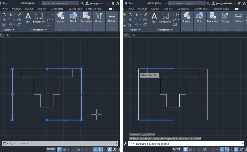
Explode
The Explode operation allows you to edit and modify individual components by breaking an object into its constitutive elements. These elements can be lines, shapes, polygons, or areas.
- Click on the Explode icon in the Modify tab or type in the word “Explode” in the command bar.
- Select the area or part of the object you want to explode, the selected part will be highlighted in blue. Then press Enter.
- Each element of the selected area should be isolated from the main compounded object. Verify by clicking any point or line in the given area.
Assembly Operations
Join
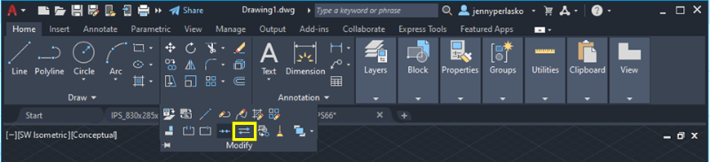
The Join operation allows the combination of two or more open or closed shapes to create a sole object with common endpoints. This tool is essential for making assemblies and can be found in 2D and 3D environments. You will find the Join tool in the Modify tab (see the picture below), or by typing in the word “Join” in the command bar at the bottom of the screen.
Move
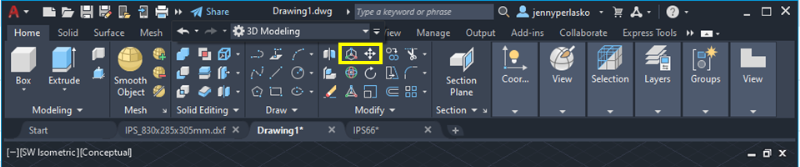
The Move operation allows you to move objects across the working space regardless of the original coordinates of the object. This tool is also essential for making assemblies. It can be found in the 2D environment (Draft and Annotations) as a crossed arrows icon located in the Modify tab, and the 3D environment (3D modeling) as Move 3D, which is represented by a crossed arrow 3D Coordinate System icon (located to the left of the 2D Moving tool).
You can also access this command by simply typing in the word “Move” in the command bar at the bottom of the screen and clicking on the desired option depending on the environment you’re working in (2D or 3D).
Rotate
The Rotate operation allows you to rotate a solid or surface around a base point or given axis of rotation to change the original position of the object. This tool aids designers in the assembling process as well, and can be found in the 3D environment (3D modeling) in the Modify tab as shown in the picture below.
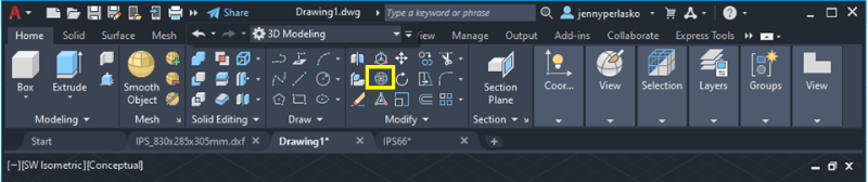
You can also access this command by simply typing in the word “Rotate” in the command bar below, clicking on “Rotate 3D,” and pressing Enter.
1. Click on the object you want to rotate and press Enter.
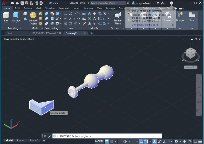
2. An atom-shaped icon will appear on top of the cursor displaying the three axes (x,y,z). Click on the axis you want to fix to rotate the object. For this, you need to apply spatial orientation skills.
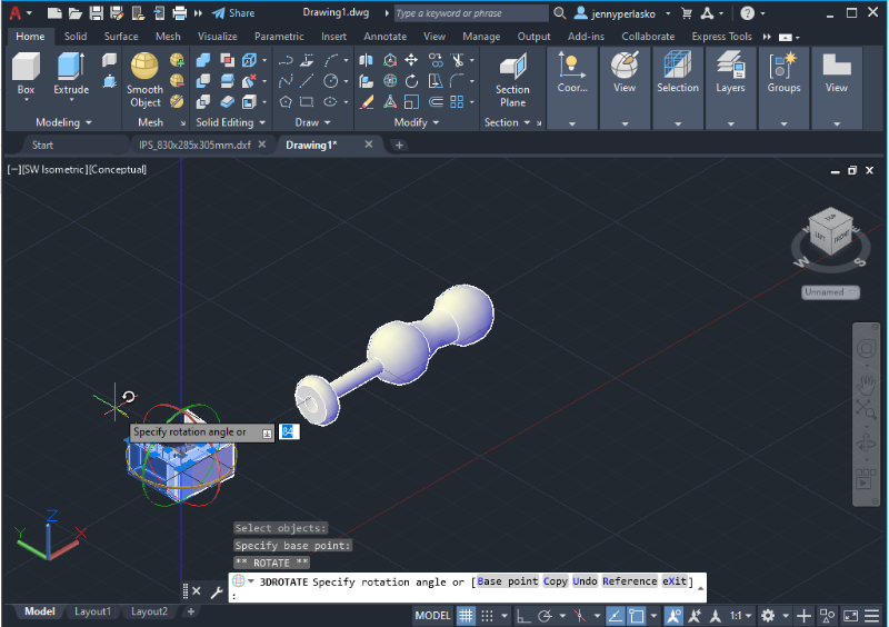
3. A dialog box will appear for you to enter the angle of rotation (from 0 to 360 degrees), then press Enter.
4. When you are done rotating the object press the ESC shortcut key.
Operations in the 3D Space
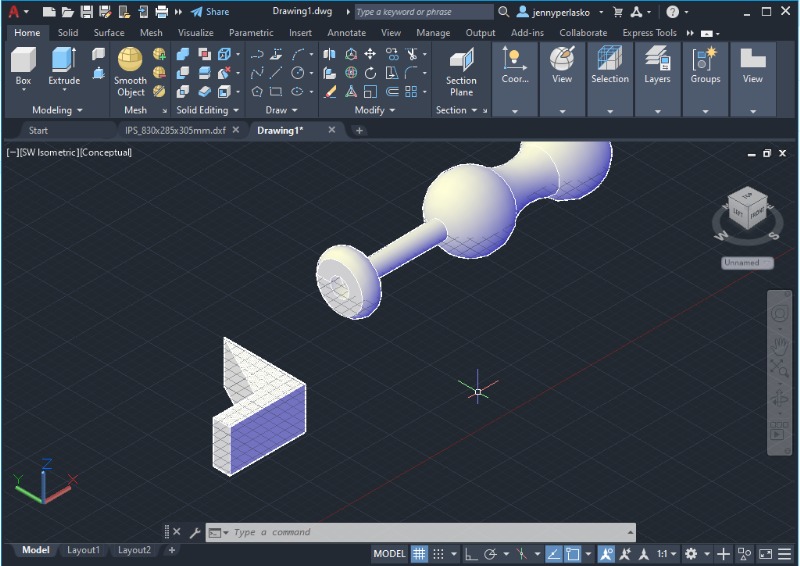
Extrude
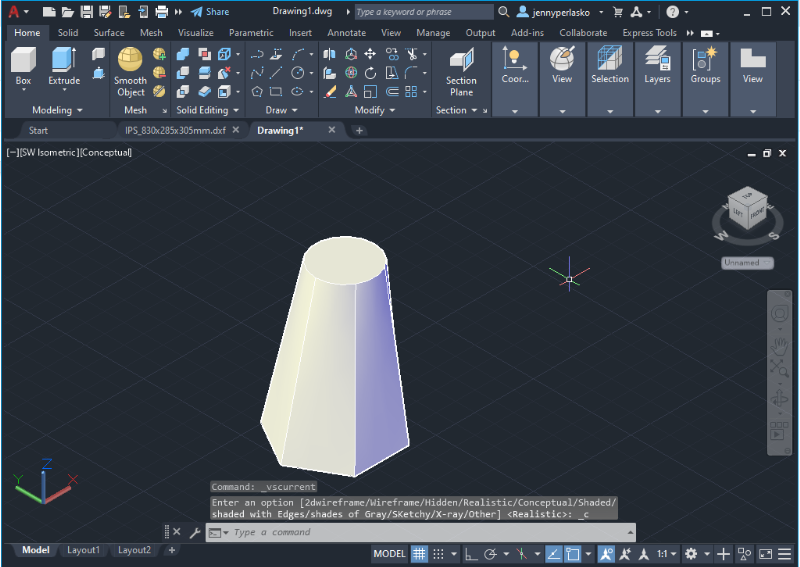
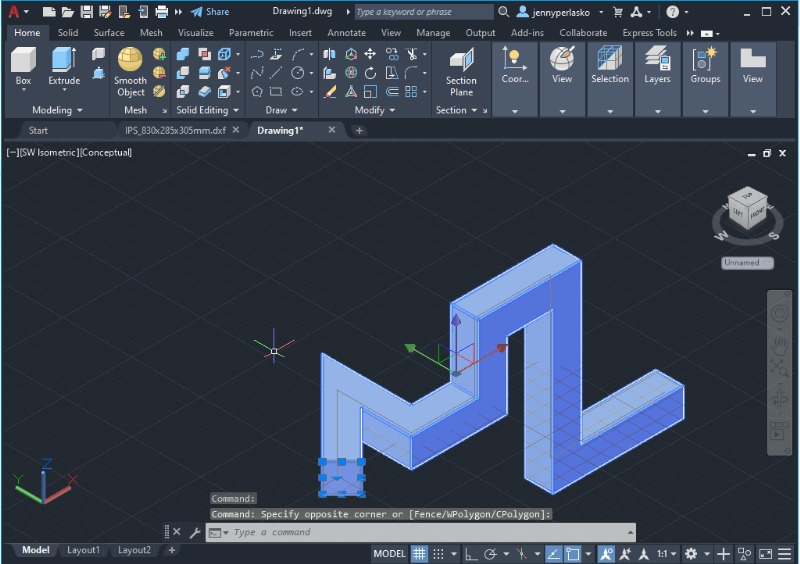
The Extrude operation allows you to add the third dimension to a 2D drawing by providing a height perpendicular to the object.
- To select the extrude operation you can use the Extrude icon located in the toolbar at Home in the Modeling tab, or you can type in the word extrude in the command bar at the bottom of the screen as you can see in the image below.
- Select the flat object (2D drawing) you want to extrude and press Enter.
- A dialog box will appear for you to enter the height of the body (it can be positive or negative depending on the axis). You can also use the mouse to establish the height. Then press Enter.
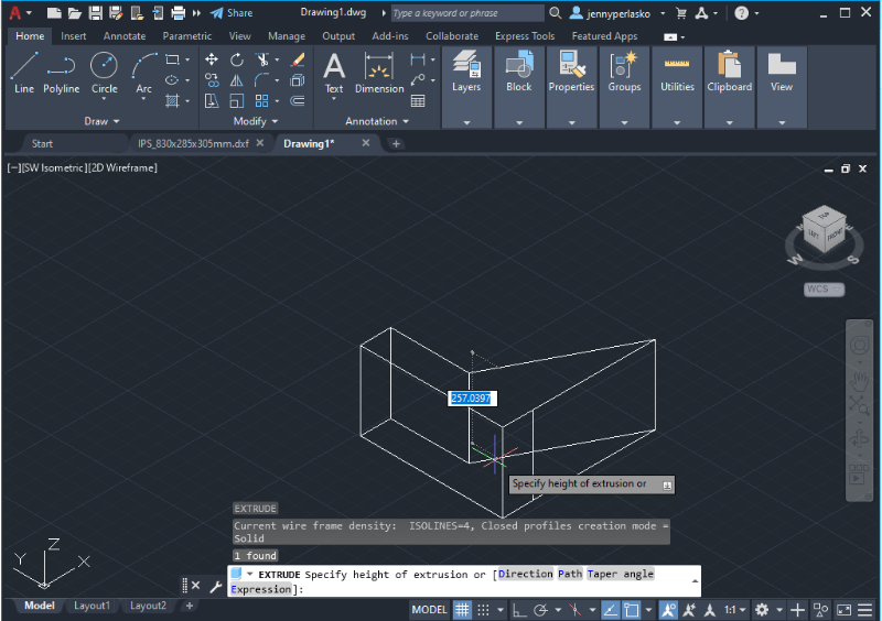
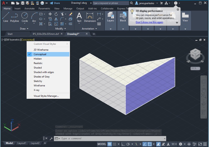
You can customize the visual style of the model by clicking the upper left corner in the drawing space below the toolbar to change the object’s perspective (2D wireframe, conceptual, realistic, etc).
Revolve
The revolve operation involves spinning an object through a specified axis enclosed by a 2D figure to create a symmetrical 3D model.
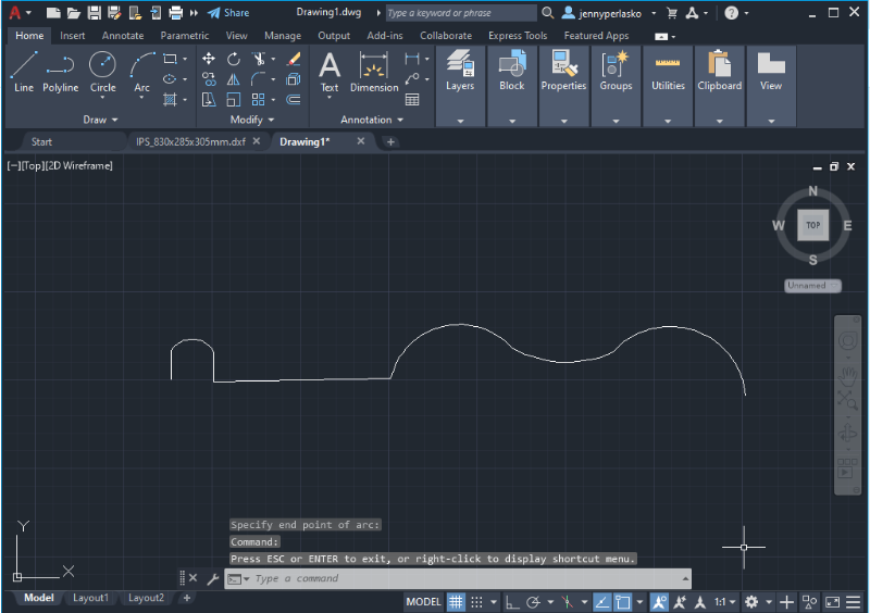
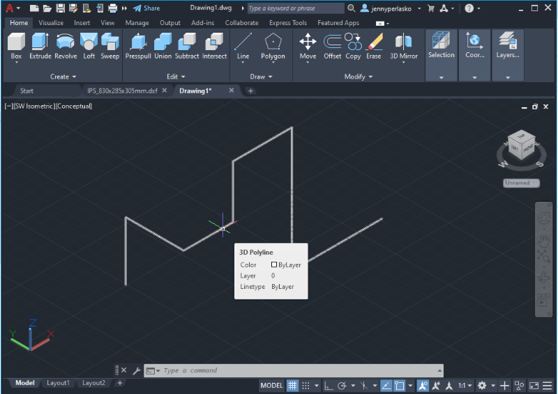
1. The first step is creating the shape of the object you want to revolve through a polyline or straight-line figure as shown in the figure below. The line or shape should be open and joined as seen in the picture below to revolve it.
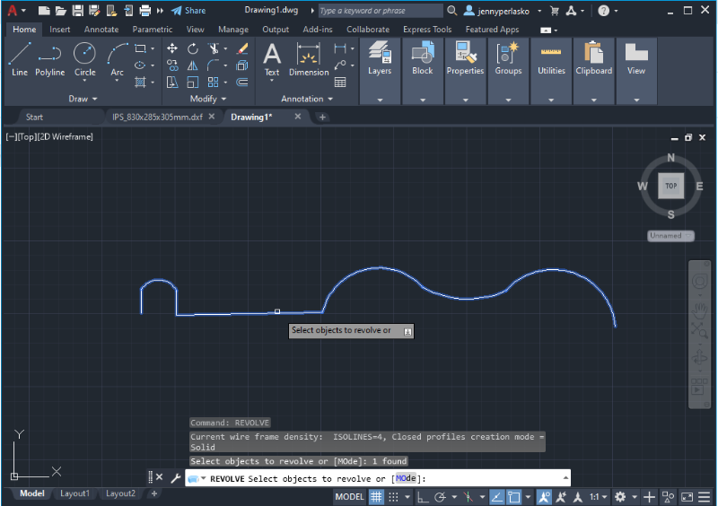
2. Type “Revolve” in the command bar at the bottom of the screen and press Enter.
3. Click on the object you want to revolve (as shown in the picture below) and press Enter.
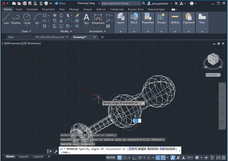
4. Indicate the axis of rotation from the initial point to the end by clicking in the working space. The rotation axis doesn’t necessarily need to meet the shape’s endpoints, you can place it at any point in the drawing space. Then press Enter.
5. A dialog box will appear for you to enter the revolution or spinning angle from 0 to 360 degrees. You can also use the mouse to establish the angle. Then press Enter.
6. The revolved object will immediately appear as a conceptual body.
Loft
The loft operation allows you to join two (or more) 2D shapes to create a 3D model or surface within the space that separates the 2D shapes. This operation is similar to extruding, however in this case the solid is created between two different cross-sections.
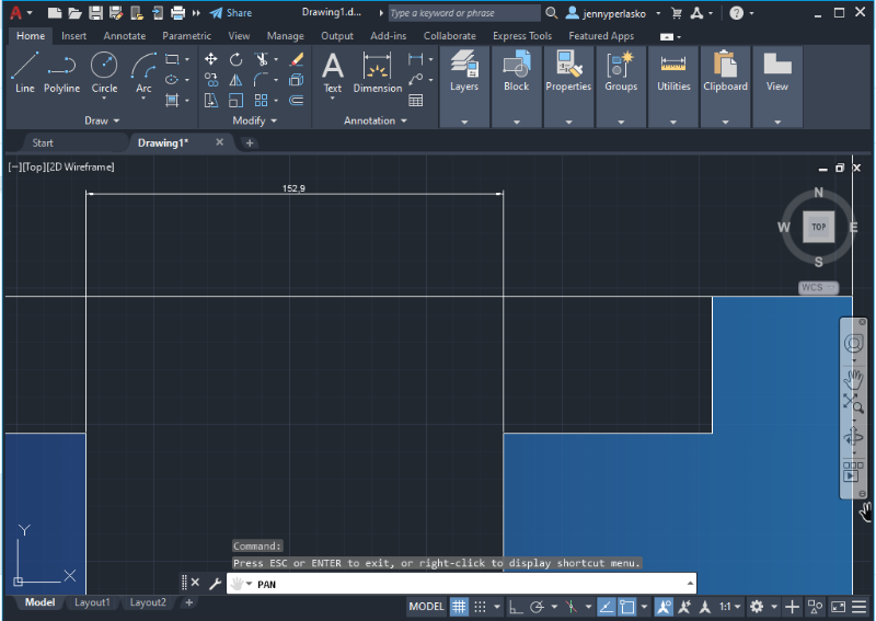
1. To use the loft operation, you need to have at least two 2D enclosed objects separated from one another in the axis perpendicular to the objects (in this case the Z axis).You can verify the location of objects in the drawing by switching the Model View and making sure both are in the same plane (in this case, the Top view would show both objects separated vertically).
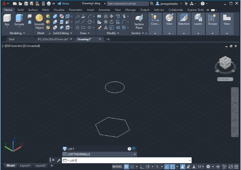
2. Use the Command bar to type in the word “Loft” and press Enter or access the Modeling tab and search for the Loft icon.
3. Select the two desired objects (one after the other), and a coordinate system will appear on top of the cursor to indicate where the loft operation will occur. Then press Enter.
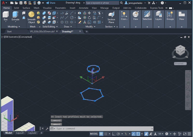
4. A solid will appear in a conceptual view (as shown in the picture below). You can always change the solid’s view by customizing the visual style in the top left corner.
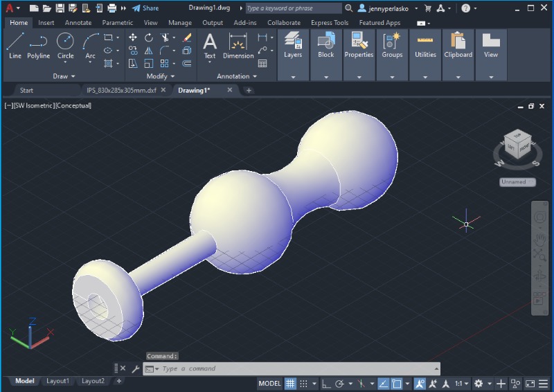
Sweep
The Sweep operation is useful for representing pípes and circuits based on an open or closed 2D path and a cross-section.
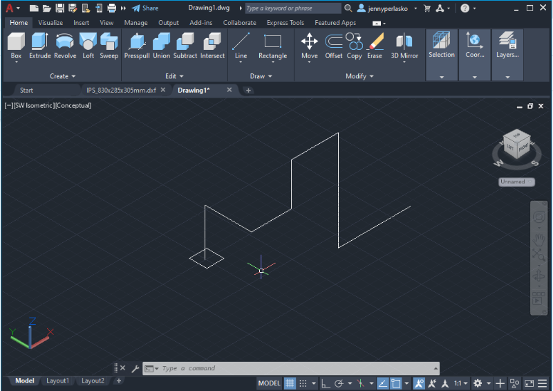
1. The first step is creating the open or closed path you want to sweep through by creating a polyline or straight-line figure as shown in the picture below.
2. Create the cross-section meeting the endpoint of the path and the center of the cross-section perpendicular to the path’s plane. You can verify the location of objects in the drawing by switching the Model View and making sure the cross-section is perpendicular to the 2D path. (in this case, the Top view model will face the cross-section).
3. Use the command bar to type in the word “Sweep” and press Enter, or use the Modeling tab and click on the Sweep icon.
4. Select the cross section and press Enter.
5. Select the path (the 2D polyline) and press Enter.
6. The solid will appear in a conceptual view as shown in the picture below.
Shell
The Shell operation turns a 3D solid into a hollow shell with a wall of wanted thickness. This is a 3D modifying operation, which is available in the toolbar in the 3D modeling environment.
1. Click on the Shell icon or type in the word “Shell” in the command bar at the bottom of the screen and press Enter to use this operation.
2. Click on the solid you want a shell for and the faces (two or more) in where the shell will be and press Enter.
3. A dialog box will appear for you to enter the width or thickness of the shell, then press Enter.

4. The shelled body should appear on the screen as a conceptual model.
Click here to learn AutoCAD with videos
Annotations and Dimensions
Annotations
- To display annotations in the workspace, head to the Annotation tab in the top bar and click on the Linear dimension icon, next to “Dimension.” This icon contains a drop-down menu with a variety of annotation options such as linear, aligned, angular, and radius, among others to annotate different types of elements in the drawing.
- Choose the appropriate type of annotation (if it’s a circle you can pick radius annotation), and then click the starting measuring point.
- The program will automatically ask you to select the ending point of the annotation, and then press Enter.
The annotation should appear immediately on the screen, and you can drag it with the mouse to the desired distance from the object. Remember to take into consideration the space needed for other annotations.
Dimensions
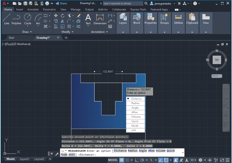
The Dimension icon is located in the Annotation tab. It’s very useful for verifying the measurements in a drawing. It displays the dimension of a given part of the sketch temporarily and works similarly to annotations. It also offers the option to measure radius and angles as well as volumes and areas of a specific object.
The procedure to measure an object is the same as Annotation, with the difference that once the dimension is shown on the screen, it will disappear after pressing Enter.
It’s a useful tool to verify dimensions in a sketch without over-annotating the drawing.
Working in the three-dimensional space will be the next step to AutoCAD user training, so it’s important to practice the basics in two-dimensional space to be prepared for more complex software tools.
Layers
Layers help you organize drawings, allowing them to temporarily suppress or hide unnecessary graphical data. Layers are a set of clear, plastic sheets that contain information regarding the model, which can be easily overlapped to recreate all the details of a drawing. The Layer command is used for different purposes to manage drawings and can be very convenient when a sketch has many objects and line types. To create a new layer you must follow these steps.
1. Click on the Layer Properties option in the main Toolbar.
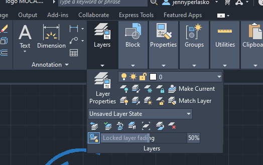
2. You will see a Layer menu with one layer named “0”. Layer 0 is the default layer that is pre-established for all drawings and usually contains some default properties. To create a new layer, click on the icon that has a yellow star.
3.Based on the options of the Quick Access menu, select the properties you want to incorporate into the new layer by clicking once in each cell. Such as name, line type, color, thickness, and visibility.
4. Select the Lightbulb icon to toggle a layer off and on.
Changing the Properties of Objects
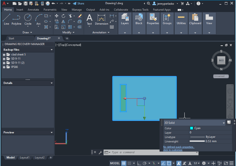
Checking an Object’s Properties
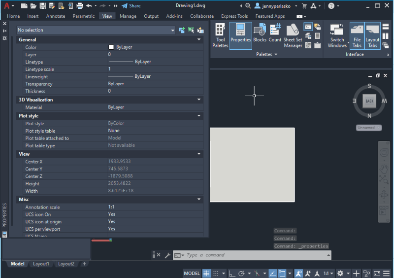
To check the properties of an object, you can right-click on it and select the Properties option, and a dialog box will appear with all the object’s details. You can also select the object and then click the View tab, and select Properties in the Palettes options.
Modifying an Object’s Properties
1. In order to modify the properties on an object, first you right-click on it and a dialog box will appear.
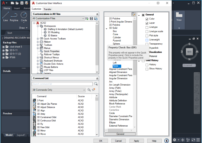
2. Click on Quick Properties and a new window should pop up on the screen to Customize User Interface.
3. You can choose which parameters you want to modify in the right column by selecting each item (color, line type, lineweight, etc).
4. Click Apply and the window will close automatically.
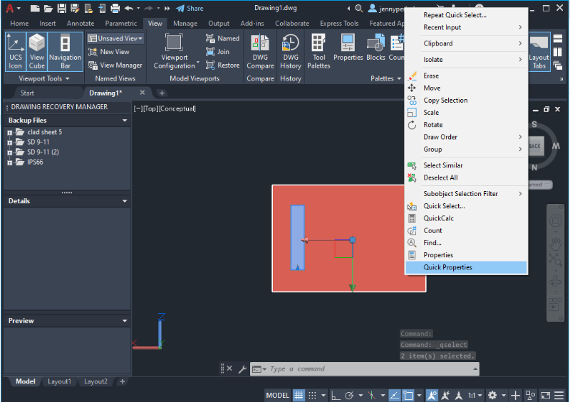
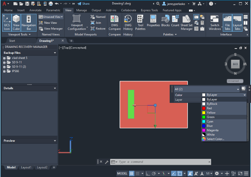
5. Right-click on the object and select Quick Selection. You should be able to see all the properties you enabled to change.
6. Apply the changes you want by choosing the layer where you want to apply the changes.
Projections, Views, and Planes
Orthographic Projection
Orthographic Projection is a technique that enables you to describe a 3D object through 2D drawings from different points of view or planes. This requires using hidden lines and projected lines in the drawing space. Here’s how to generate these lines.
- Open the tool palette that you want to use in the View Tab at the top of the screen, and select the Hidden Line Projection tool.
- In a 3D view (3D modeling or 3D basics) select one or more objects that you want to use to create your hidden line projection and press Enter. Take into consideration that orthographic projection is only possible with 3D objects.
- Specify an insertion point in your current drawing for the 2D hidden line projection. For example, select the right corner of a rectangle to project that face (plane).
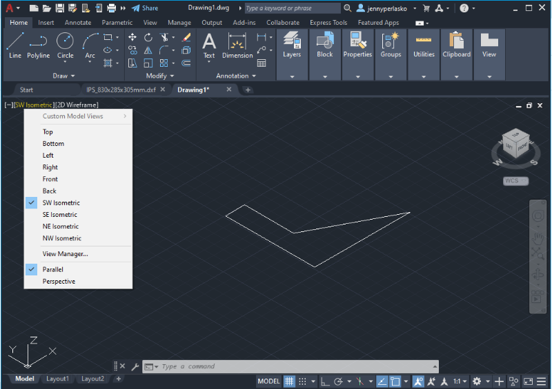
Customize View
You can customize the model view by clicking the upper left corner in the drawing space below the toolbar to change the object’s perspective. It will show all the available options: top, bottom, right, left and all isometric views.
Saving Files
File Types
AutoCAD works with its own file type, DWG, which contains all the drawings’ information. It also allows you to export files such as DXF to Adobe as PDFs, Adobe Illustrator, or Corel Draw.
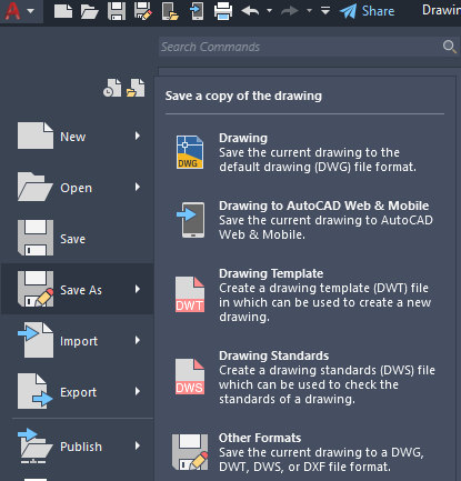
Save as DXF Format
- Click File at the top of the screen and select the “Save As” option.
- In the “Save Drawing As” dialog box, in the Files Type box, select DXF as the format.
- Select a folder and enter a file name.
- Click Save or simply press Enter.
Blocks and Libraries
Blocks are pre-designed figures or shapes aimed to help you reduce drawing time for repetitive objects. They are generally used in industrial fields (like architecture and civil engineering) to maintain a normalized format in drawings in terms of presentation and sequence. Libraries are virtual spaces where those figures and shapes are stored and classified to give easy access to the user.
Grow Your AutoCAD Expertise with CADLabWorld
Visuals and dynamic content are crucial to learning any new skill, and although the basics of AutoCAD were thoroughly covered in this free lecture, there’s still a lot to learn to master this software. In this sense, CADLabWorld offers a unique AutoCAD Online Training Course for beginners.
This course offers a total of eight hours of intensive lessons for you to master all AutoCAD tools and become a skilled CAD designer. All the information given throughout the course (divided into 11 chapters) is explained in very straightforward language, making it easy for anyone to understand it.
In addition, all participants receive an original Complete AutoCAD Strategy Guide, which provides valuable information that you can refer to long after you have completed the course. In this sense, you will have lifetime access to detailed information regarding AutoCAD, as well as tips and much more.