Developed by Autodesk, AutoCAD 3D made its debut as an extension of the original AutoCAD software, which has been an industry standard since its introduction in 1982. Over the years, AutoCAD 3D has evolved through numerous upgrades and iterations, continuously incorporating the latest in design technology to meet the ever-growing demands of the design world. AutoCAD 3D’s impact spans across a myriad of industries, proving itself as an indispensable tool in the toolkit of professionals across the globe. In architecture, it has revolutionized the way buildings are conceptualized, allowing architects to create detailed 3D models that simulate real-world structures with astonishing accuracy. AutoCAD 3D’s versatility even extends to the entertainment industry, where it is used to design intricate set pieces, props, and even entire stages for film, television, and theater productions. This capacity to bridge various creative and technical fields underscores AutoCAD 3D’s unparalleled flexibility and its crucial role in bringing imaginative concepts to tangible realities.
- 1 AutoCAD 3D capabilities
- 2 Getting Started with AutoCAD 3D
- 3 Basic 3D Modeling Techniques in AutoCAD
- 4 Rendering and visualization in AutoCAD
- 5 Conclusion
AutoCAD 3D capabilities
AutoCAD 3D is the superstar when it comes to whipping up super precise and detailed 3D models. It’s got all the tools you could ever want, whether you’re crafting simple shapes or diving into the nitty-gritty of complex buildings and machinery. You’ve got control over tons of settings to get everything just right, which is perfect for those projects where every little detail matters.
In essence, AutoCAD 3D embodies the convergence of creativity and precision, empowering professionals across industries to explore new horizons, innovate, and materialize their visions with unparalleled accuracy and efficiency. Whether you’re an architect, engineer, designer, or artist, AutoCAD 3D offers the tools and flexibility to push the boundaries of what’s possible, making it a cornerstone of modern design and manufacturing.
What is AutoCAD: Functions and operation guide for 2DCAD beginners
Getting Started with AutoCAD 3D
Getting started with AutoCAD 3D? For information on pricing and system requirements see our article on getting started for beginners You’ll find its setup pretty user-friendly. Here’s the lowdown:
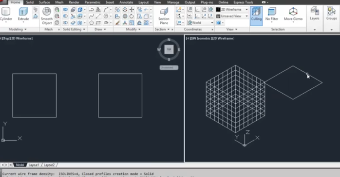
User Interface Overview
Here’s a breakdown of the essentials.
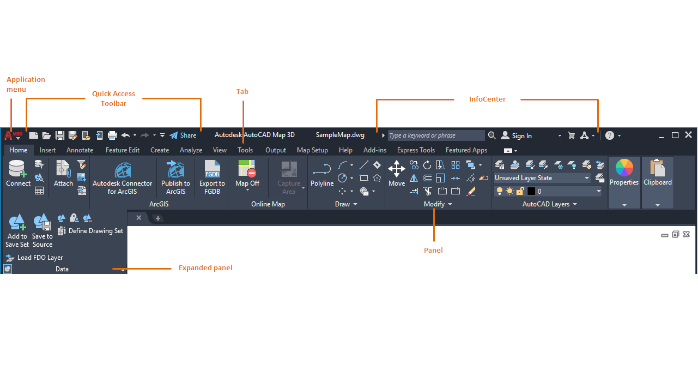
Ribbon
Picture a handy toolbox at the top of your screen—that’s your Ribbon. It’s packed with tabs that sort all your drawing and modeling commands into neat little categories. The Ribbon is at the top of the interface and contains multiple tabs, each with its own set of tools grouped by functionality. This is where you access most of the drawing and modeling commands.
- Home Tab: This is your go-to spot for the everyday tools you’ll need, perfect for when you’re making basic 3D shapes like boxes or cylinders, tweaking surfaces, or adjusting your creations. This tab contains the most commonly used tools, such as those for creating basic 3D solids, 3D surfaces, mesh objects, and for modifying and editing these objects (move, rotate, scale, etc.).
- Insert: This tab allows you to insert external references, blocks, and other files into your drawing.
- Annotate: Here, you can find tools for adding text, dimensions, and other annotations to your 3D model.
- View: This tab provides tools for changing the viewpoint, visual styles (wireframe, shaded, etc.), managing viewports, and creating camera views.
- Manage: Contains tools for managing applications, customizing settings, and accessing CAD standards.
- Output: This tab is used for plotting, publishing, and exporting your designs.
- Mesh Modeling: Specifically for working with mesh models, this tab offers tools for creating and modifying mesh objects.
- Solid Editing: Offers tools for editing solid objects, including boolean operations (union, subtract, intersect), and editing faces, edges, and vertices of solids.
- Surface Editing: Contains tools for creating and editing surface objects, allowing for complex surface modeling.
- Parametric: This tab includes tools for defining geometric and dimensional constraints that control the behavior of objects.
- Collaborate: Provides access to collaboration tools and settings for working with others on projects.
- Express Tools: A collection of additional tools and commands that extend the functionality of AutoCAD.
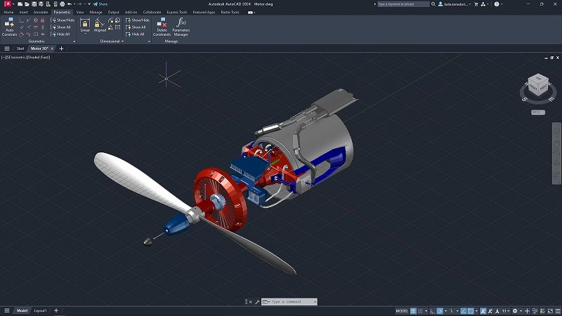
ViewCube
The ViewCube is a navigational tool displayed in the top-right corner of the workspace. It allows you to quickly rotate and orient your view of the 3D model in any direction.
Command Line
Located at the bottom of the screen, the command line is where you can input commands directly, view prompts, and access a history of used commands. It’s a powerful feature for experienced users who prefer typing commands.
Basic Navigation
Getting around your 3D model is a breeze once you get the hang of it. Here’s how you do it:
- Pan: Click and hold the mouse wheel, then move the mouse to pan the view. This moves your view up, down, left, or right.
- Zoom: Scroll the mouse wheel to zoom in or out. This helps you focus on details or see the bigger picture of your model.
- Orbit: Hold the Shift key and press the mouse wheel, then move the mouse to orbit around the model. This allows you to view the model from different angles and perspectives.
Understanding these navigation tools is crucial for efficient 3D modeling in AutoCAD. As you become more familiar with the interface and navigation, you’ll find it easier to create and edit complex 3D models. Practice using these tools to gain confidence in your abilities and take full advantage of what AutoCAD 3D has to offer.
Basic 3D Modeling Techniques in AutoCAD
Now let’s actually create a 3D model with AutoCAD!
Primitive Shapes in AutoCAD
In AutoCAD, creating primitive shapes is straightforward. Here’s how to create basic 3D shapes like boxes, spheres, and cylinders:
- Boxes (Cubes): Use the BOX command. You’ll be prompted to specify the corner of the box and then the opposite corner. The height can be defined by moving the cursor upward and clicking at the desired height.
- Spheres: Utilize the SPHERE command. Click to set the center point and then drag or specify the radius.
- Cylinders: Use the CYLINDER command. After specifying the center point of the base, set the radius and then the height.
In AutoCAD, these shapes can be further modified using various tools like MOVE, ROTATE, and SCALE to adjust their position, orientation, and size.
Extruding 2D Shapes in AutoCAD
Extruding in AutoCAD transforms 2D shapes into 3D forms. Follow these steps:
- Create a 2D Shape: This could be a circle, rectangle, or any closed polyline. Use commands like CIRCLE, RECTANG, or POLYLINE.
- Extrude the Shape: Use the EXTRUDE command. Select the 2D shape and then specify the height of extrusion by typing a value or dragging the cursor.
- Adjusting the Extrusion: You can edit the extrusion by selecting the object and using grips or by entering new values in the properties panel.
Boolean Operations in AutoCAD
Boolean operations in AutoCAD are performed using different commands. Here’s how to use them:
- Union: Use the UNION command to combine two or more 3D solids into one. Select the objects you wish to unite and press Enter.
- Subtract (Difference): Use the SUBTRACT command to cut one solid with another. Select the solid you want to keep first, press Enter, then select the solid you want to subtract.
- Intersect: Use the INTERSECT command for creating a 3D solid from the overlapping volume of two or more solids. Select the solids, then press Enter.
In each of these operations, the original shapes are replaced by the resulting 3D model. You can undo or modify these operations if necessary.
Using these basic techniques in AutoCAD, you can start building complex 3D models. These foundational skills are vital for precision modeling and are widely applicable across various design and engineering disciplines. As with any software tool, practice and experimentation are key to mastering AutoCAD’s capabilities.
Surface Modeling
Surface modeling in AutoCAD is a technique used to create complex surfaces and forms. This approach is particularly beneficial for designing curved or irregular shapes that require a high level of precision and detail. Surface modeling allows designers to manipulate a surface’s control points, edges, and faces to craft intricate geometries that might be challenging to achieve with other modeling techniques. By using tools such as ‘Networks’, ‘Sweeps’, ‘Lofts’, and ‘Revolve’, designers can generate smooth and continuous surfaces. These tools enable the creation of everything from automotive exteriors to intricate architectural elements, offering the flexibility to model forms that closely match the designer’s vision.
Mesh Modeling
Mesh modeling in AutoCAD is geared towards more organic, flexible shapes, akin to what one might find in nature or in art. Mesh models are made up of vertices, edges, and faces that form a polyhedral structure. This method is particularly useful for models that require non-uniform modifications, such as landscapes, human figures, or other complex organic forms. Mesh modeling tools in AutoCAD allow for a more sculptural approach to 3D modeling, where the designer can push, pull, extrude, and refine the mesh to achieve the desired shape. The flexibility of mesh modeling makes it an excellent choice for preliminary designs or when an approximate model is sufficient for visualization purposes.
1. Access Mesh Commands
You can find mesh creation tools on the Mesh tab on the Ribbon. If you’re using a different workspace, you might need to switch to the 3D Modeling workspace to see these tools. The Mesh tab includes a variety of primitives (like boxes, spheres, cylinders, cones, etc.) and other mesh creation tools.
2. Create Mesh Primitives
Start with mesh primitives as the building blocks of your model. For instance, to create a mesh box, you can use the BOX command and specify the corner points and height. Other primitives include SPHERE, CYLINDER, CONE, TORUS, and more, each with its own set of options to define dimensions and complexity.
3. Modify Meshes
After creating a mesh object, you can modify it using various tools under the Mesh tab. These include:
- Smooth and Refine: To increase the level of detail and smoothness of your mesh.
- Crease and Uncrease: To define sharp edges or remove them.
- Collapse: To simplify mesh geometry by reducing detail.Tools for editing mesh faces, edges, and vertices are also available, allowing for detailed shaping and adjustment.
4. Use the GIZMO for Manipulation
The 3D Move (GIZMO) tool helps in manipulating mesh objects directly in the 3D space. It allows for moving, rotating, and scaling objects easily.
5. Convert to Mesh
You can convert other 3D objects (solids, surfaces) to mesh objects using the CONVERTTOMESH command. This gives you the flexibility to start with a solid or surface model and then refine it as a mesh.
6. Sculpt Meshes
The SCULPT command can be used to create a solid from the enclosed volume of overlapping or intersecting mesh objects, offering a way to combine simple shapes into complex models.
Solid Modeling
Solid modeling is the cornerstone of 3D modeling in AutoCAD for creating detailed and accurate 3D objects. Unlike surface or mesh modeling, solid modeling focuses on constructing models with volume and mass, making it ideal for engineering and manufacturing applications. Solid modeling tools in AutoCAD provide an array of functionalities to build complex models through Boolean operations such as union, subtract, and intersect. These operations allow designers to combine or remove solid shapes to form new geometries. Solid modeling is essential for creating parts and assemblies that can be accurately analyzed, manufactured, and tested in the real world. It supports precision in dimensions and tolerances, enabling the creation of detailed technical drawings directly from the 3D model.
1. Access Solid Modeling Tools
Solid modeling tools are located in the Solid tab on the Ribbon in the 3D Modeling workspace. If you’re in a different workspace, switch to the 3D Modeling workspace to access these tools.
2. Create Solid Primitives
Begin by creating basic solid shapes. Use commands like BOX, SPHERE, CYLINDER, CONE, and PYRAMID to create these primitives. You’ll specify dimensions and placement in the drawing area. Primitives serve as the foundation for more complex models.
3. Use Boolean Operations
Boolean operations allow you to combine or subtract solid objects to create new shapes. These operations are fundamental to creating complex models from simpler ones. The primary Boolean commands are:
- UNION: Combines two or more solids into a single object.
- SUBTRACT: Uses one solid to cut away parts of another.
- INTERSECT: Creates a solid from the overlapping volume of two solids.
4. Modify Solids
AutoCAD provides a range of tools to edit and refine solid objects. These modifications can significantly change the appearance and complexity of your model:
- EXTRUDE: Extend a 2D shape into a 3D solid by extrusion.
- REVOLVE: Create a solid by revolving a 2D shape around an axis.
- PRESSPULL: Dynamically modify the geometry of solids or create solids by extruding 2D shapes.
- FILLET and CHAMFER: Apply rounded or angled edges to the corners of solids.
5. Solid Editing Tools
AutoCAD’s solid editing tools allow for more detailed manipulation of solid models, including face, edge, and vertex editing. You can move, rotate, scale, copy, offset faces, and more. Use commands like SOLIDEDIT to access these options.
6. Use the GIZMO for Direct Manipulation
The 3D Move (GIZMO) tool is also useful for directly manipulating solid objects, allowing for intuitive positioning, rotation, and scaling in 3D space.
Rendering and visualization in AutoCAD
Rendering and visualization in AutoCAD are crucial aspects that transform simple 3D models into visually stunning and realistic representations. These processes involve the application of materials and textures, the setup of lighting, and the use of rendering techniques to achieve photo-realistic images. Let’s dive into each of these components:
Materials and Textures
Materials and textures are fundamental in adding realism and depth to your 3D models. Materials define the color, reflectivity, transparency, and texture of the surfaces in your model, simulating real-world materials such as metal, glass, wood, and fabric.
Applying Materials
In AutoCAD, you can apply materials to individual objects or layers. To do this, open the Materials Browser by clicking on the “Materials Browser” button on the Render tab. Here, you can choose from a library of predefined materials or create your own by specifying properties like color, luminance, and reflectivity. Drag and drop the selected material onto your object or layer in the drawing.
Customizing Textures
Textures add surface detail to the materials, such as wood grain or brick patterns. In the Materials Browser, you can edit a material to customize its texture by adjusting its scale, rotation, and offset. Textures can be based on bitmap images or procedural patterns. For more detailed customization, use the texture mapping controls to align the texture properly on complex geometries.
Lighting Setup
Lighting is a powerful tool to enhance the visual impact of your models by simulating natural or artificial light sources. Proper lighting setup can highlight textures, cast shadows, and define the mood of the scene.
Types of Lights
AutoCAD offers several types of lights, including point lights, spotlights, and distant lights. Point lights emit light in all directions from a single point, simulating bulbs or small light sources. Spotlights project light in a specific direction and angle, ideal for highlighting or creating focused lighting effects. Distant lights simulate sunlight, providing parallel light rays across the entire scene.
Configuring Lights
To add a light, go to the Render tab and select the type of light you want to add. Once placed, you can adjust its properties, such as intensity, color, and direction. Experiment with different lighting setups to see how they affect the appearance of your model. Remember, the key to effective lighting is balancing between shadows and highlights to create depth and contrast.
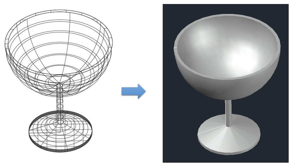
Photo-realistic Rendering

Rendering is the process of generating a high-quality image from your 3D model. It calculates light reflections, refractions, and shadows to produce a photo-realistic image that closely resembles real-life visuals.
Rendering Process
To start rendering, go to the Render tab and click on the “Render” button. Before rendering, ensure that your materials and lighting are correctly set up. You can choose from various render presets, ranging from draft quality for quick previews to high quality for final presentations. The rendering process can take from a few seconds to several hours, depending on the complexity of the scene and the chosen settings.
Adjusting Render Settings
For more control over the final output, you can adjust the render settings, such as resolution, quality, and exposure. Higher resolution and quality settings will produce better images but will take longer to render. Exposure settings can be tweaked to simulate different times of day or lighting conditions.
Post-Processing
After rendering, you may want to adjust the image further using post-processing tools. AutoCAD includes basic adjustments like brightness and contrast, but for more advanced editing, you can use external image editing software.
Through the careful application of materials and textures, strategic lighting setup, and detailed rendering, you can create stunning and photo-realistic images in AutoCAD. These images can be used for presentations, marketing materials, or simply to visualize and refine your designs before they are built. Practice and experimentation are key to mastering rendering and visualization in AutoCAD, so don’t hesitate to explore different techniques and settings to achieve your desired outcomes.
Conclusion
In conclusion, AutoCAD 3D stands as a pivotal tool in the CAD industry, offering unparalleled capabilities for 3D modeling, rendering, and design across various sectors. From creating simple geometric models to executing complex designs with precision and efficiency, AutoCAD 3D equips professionals with the necessary tools to bring their visions to life. Whether you’re an architect, engineer, or designer, this guide serves as your stepping stone into the vast possibilities AutoCAD 3D offers. Embrace the journey of mastering AutoCAD 3D’s functionalities, and let your creativity and technical skills flourish. Remember, the only limit in the world of 3D design is your imagination.