SolidWorks Electrical CAD simplifies schematic design with an intuitive interface, delivering faster results. Its real-time, bi-directional integration with SolidWorks 3D CAD enables automatic wire routing, accurate length calculations, and seamless interference detection.
- 1 What is SolidWorks Electrical?
- 2 SolidWorks Electrical Overview
- 3 Download and Install the SolidWorks Electrical Version
- 4 Understanding SolidWorks Electrical Schematics
- 5 Components and Symbols in SolidWorks Electrical
- 6 Understanding the Basics of SolidWorks Electrical
- 7 PLCs and Automation in SolidWorks Electrical
- 8 What is SolidWorks Electrical 3D?
- 9 FAQ
- 10 Conclusion
What is SolidWorks Electrical?

SolidWorks Electrical is a software tool for designing electrical schematics and wiring diagrams. It integrates with SolidWorks 3D CAD for seamless coordination between electrical and mechanical designs. The software enhances efficiency, accuracy, and collaboration in engineering projects.
SolidWorks Electrical is widely used in industries such as manufacturing, automotive, aerospace, and consumer electronics.
SolidWorks Electrical Overview
SolidWorks Electrical is a powerful design software that streamlines the creation of electrical schematics, wiring diagrams, and control systems. It offers a user-friendly interface, comprehensive parts libraries, and tools for automating tasks such as generating reports and documentation.
| Aspect | Details |
| Purpose | Specialized software for designing electrical systems and schematics. |
| Features | Intuitive interface, automatic wire routing, real-time integration with SolidWorks 3D CAD, parts libraries, and design rule checks. |
| Use Cases | Creating electrical schematics, wiring diagrams, control systems, and ensuring integration with mechanical designs. |
| Accessibility | Seamless integration with SolidWorks 3D CAD, cloud-based collaboration tools, and real-time updates. |
| Benefits | Increases design accuracy, reduces errors, speeds up development, and improves collaboration between electrical and mechanical teams. |
| Ideal For | Electrical engineers, designers, and teams working in manufacturing, automotive, aerospace, and consumer electronics industries. |
Key Features of SolidWorks Electrical
Here is a concise summary of SolidWorks Electrical’s features, including Schematic Design, Component Libraries, Wiring, Panel Layout, 3D Integration, and PLC/I/O Management.
Schematic Design
Create electrical schematics with ease using a comprehensive set of tools for drawing circuits and wiring.
Component Libraries
Access a vast library of electrical components, including symbols, parts, and manufacturers’ data.
Wiring and Cabling
Automatic wire numbering, cable routing, and generating wire lists for better organization.
Panel Layout Design
Design and plan control panel layouts, with the ability to create precise 2D and 3D representations.
3D Integration
Integrate electrical designs with 3D models to route cables and verify design functionality.
PLC and I/O Management
Design programmable logic controller (PLC) layouts and manage I/O connections within electrical projects.
Automatic Reports and Bill of Materials (BOM)
Automatically generate detailed reports, BOMs, and terminal strip layouts directly from your schematic.
Cross-Referencing
Automatically create cross-references for components across multiple schematics, enhancing accuracy.
Design Validation and Error Checking
Perform design validation to detect errors and ensure compliance with industry standards.
Collaboration and Data Sharing
Share projects with team members using cloud-based tools or directly within the SolidWorks PDM system.
Real-time Synchronization
Keep 2D and 3D designs in sync, automatically updating changes in both environments.
Custom Component Creation
Easily create and manage custom components and symbols for specialized projects.
Integration with Other SolidWorks Products
Seamless integration with SolidWorks Mechanical CAD (MCAD) for comprehensive design and engineering.
Advanced Electrical Documentation
Quickly generate detailed electrical documentation like wiring diagrams, terminal diagrams, and schematics.
Download and Install the SolidWorks Electrical Version
To download and install SolidWorks Electrical, visit the official SolidWorks website or authorized distributor. Once you access the download section, choose the version of SolidWorks Electrical that fits your system and follow the on-screen instructions. After downloading the setup file, run it and complete the installation process by selecting your preferences and license options. Ensure your system meets the minimum requirements for a smooth installation. You can refer to SolidWorks website to download it.
Understanding SolidWorks Electrical Schematics

An electrical schematic is a type of technical drawing that shows how electrical components are connected in a system. Unlike wiring diagrams that focus on physical layout, schematics focus on the electrical flow, showing how components interact within the system. Common components in these diagrams include resistors, capacitors, transistors, switches, and power sources.
The layout closely resembles that of AutoCAD Layout. For more details, you can refer to the page below.
Importance of Electrical Schematics
Schematics are essential for designing, troubleshooting, and maintaining electrical systems. They provide a clear blueprint of component connections and functionality. Engineers and technicians use them to ensure efficiency, diagnose issues, and optimize performance.
System Design
Schematics are essential for designing electrical circuits. Engineers use these diagrams to plan how different components will interact and function together. Whether designing a new circuit or upgrading an old one, schematics provide a clear overview of the system’s functionality.
Troubleshooting and Maintenance
When electrical equipment fails, the first step is often to analyze the schematic. A thorough understanding of how the system works allows technicians to pinpoint potential issues, identify faulty components, and test the system methodically. This reduces the time spent troubleshooting and ensures the problem is fixed quickly.
Safety
Working with electrical systems can be dangerous. A well-documented schematic can help prevent mistakes and ensure that electrical installations meet safety codes and standards. It provides a clear picture of the system’s voltage and current flow, helping prevent accidents such as overloads, short circuits, or electrical fires.
Efficient Communication
Schematics serve as a universal language for engineers and technicians. No matter where in the world the schematic is being used, the standardized symbols allow individuals to communicate the design and function of electrical systems clearly.
Components and Symbols in SolidWorks Electrical

SolidWorks Electrical is a powerful tool used for creating electrical schematics and documentation. The software offers a range of features that streamline the design and layout of electrical systems. One of the key tasks in electrical design is the addition of components and symbols, which are essential for building accurate and effective electrical circuits. This article will guide you through the process of adding components and symbols in SolidWorks Electrical.
Components
These are individual elements in an electrical circuit such as resistors, switches, cables, connectors, circuit breakers, etc. Each component has specific attributes, such as part numbers, ratings, and other technical details.
Symbols
These represent the graphical representation of components on a schematic diagram. Symbols are standardized drawings that make it easier for engineers and electricians to understand how components are connected within a circuit.
How to Add Components in SolidWorks Electrical?
Here are the ways in which you can add components into your SolidWorks Electrical project.
Open Your Project
Start SolidWorks Electrical and open your existing project or create a new one by selecting File > New.
Access the Component Library
In the SolidWorks Electrical interface, you’ll find the Component Library. It can be accessed through the Task Pane or the Component tab on the ribbon.
Browse the Library
Browse through the pre-built library of components. You can search by category (e.g., switch, relay, etc.), or use the search bar to find a specific part.
Select a Component
Once you locate the component you need, select it. You can either drag it directly onto your schematic or right-click to place it in the drawing.
Place the Component
After selecting the component, click on the schematic area where you want to place it. If necessary, adjust its orientation before confirming placement.
Edit Component Properties
Right-click on the component and select Properties to open the properties window. Here you can modify technical data such as part numbers, ratings, wire connections, and more.
Repeat the Process
Continue adding components for the rest of your circuit by following the same steps. SolidWorks Electrical allows you to add multiple components in a short amount of time, ensuring a fast workflow.
Understanding the Basics of SolidWorks Electrical
Wires, cables, and connections are fundamental components of modern electrical and electronic systems. From the simplest household appliances to complex industrial machinery, these elements are essential for transmitting power, signals, and data. Understanding the differences between wires and cables, as well as how connections work, is crucial for anyone working with electrical systems.
Wires
A single, conductive strand, typically made of metal such as copper or aluminum, used to transmit electrical current or signals. Unlike cables, a wire is usually insulated with a protective coating but can also be bare in certain applications. Wires are commonly used in simpler electrical connections and internal circuits where lower current or single signal transmission is needed.
Solid Wires
Made from a single piece of metal, these wires are durable and offer a stable connection. They are typically used for permanent installations where the wire won’t be moved frequently.
Stranded Wires
Composed of multiple thin strands of metal twisted together, stranded wires are more flexible than solid wires. They are used in situations where flexibility and bending are necessary, such as in flexible power cords or automotive wiring.
Cables
Consists of multiple wires bundled together, often with an outer protective layer (insulation). Cables are designed to carry more current or multiple signals at once, making them ideal for more complex electrical systems. There are several types of cables:
Power Cables
These are used to transmit electrical power from one point to another, such as from a power source to an appliance or machinery.
Data Cables: Designed for data transmission, these cables include twisted pairs, coaxial cables, and fiber optic cables. Common examples include Ethernet cables (used for networking) and HDMI cables (used for video and audio).
Shielded Cables
These cables have an additional layer of shielding to protect against electromagnetic interference (EMI). They are used in sensitive electronics where data integrity is important.
PLCs and Automation in SolidWorks Electrical

In SolidWorks Electrical, automation and Programmable Logic Controllers (PLCs) play a significant role in simplifying electrical design, particularly in control systems and industrial automation. Here’s how PLCs and automation are integrated into the software:
- PLC Symbol Libraries
- Automation in Wiring Diagrams
- PLC I/O Mapping
- Automation with Intelligent Components
- PLC Ladder Logic Integration
- Automatic Bill of Materials (BOM) for PLCs
- Control Panel Design
- Real-Time Collaboration
What is SolidWorks Electrical 3D?

SolidWorks Electrical 3D is an add-on to SolidWorks CAD software that allows electrical engineers to seamlessly integrate their electrical designs into the 3D mechanical environment. This integration combines the benefits of electrical schematic design with the spatial and geometrical advantages of 3D CAD modeling.
Refer to the link below for more details.
With SolidWorks Electrical 3D, users can link electrical components such as wires, connectors, and devices directly into their 3D models. This connection ensures that the mechanical and electrical aspects of the design are considered together, helping to identify potential issues early in the design process and reduce costly errors in manufacturing.
Key Features of SolidWorks Electrical 3D
SolidWorks Electrical 3D enables seamless collaboration between electrical and mechanical teams. Both teams can work on the same design simultaneously, making real-time updates to the 3D model or electrical schematic while staying synchronized. This reduces communication gaps and accelerates the overall design process.
Real-Time Collaboration
One of the standout features of SolidWorks Electrical 3D is its ability to allow for real-time collaboration between electrical and mechanical teams. Both teams can work on the same design simultaneously, making changes in the 3D model or electrical schematic while keeping each other updated on the progress. This eliminates communication gaps and accelerates the design process.
Integration with SolidWorks 3D CAD
SolidWorks Electrical 3D is fully integrated with SolidWorks 3D CAD, offering a unified platform for mechanical and electrical design. This means that designers can quickly move from schematic diagrams to 3D models with minimal hassle. The synchronization between the two allows electrical components to be placed accurately within the mechanical design and routed without conflicts.
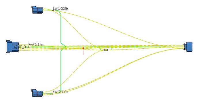
3D Routing and Visualization
The 3D routing feature allows engineers to easily place cables, wires, and electrical components in the 3D environment. The software automatically generates realistic 3D views of the electrical systems, providing a clear and intuitive visualization of how electrical systems interact with the mechanical parts.
Collision Detection
By integrating electrical systems into the 3D mechanical model, SolidWorks Electrical 3D offers real-time collision detection. Engineers can quickly spot interference between electrical components and mechanical parts, ensuring that the final design will be error-free and manufacturable without costly revisions.
Automatic Bill of Materials (BOM)
As electrical systems are designed in the 3D environment; SolidWorks Electrical 3D can automatically generate an up-to-date bill of materials (BOM). This feature streamlines the documentation process by ensuring that all components are accounted for and accurately listed in the BOM without the need for manual data entry.
Design Reuse and Standardization
SolidWorks Electrical 3D allows users to create libraries of standardized components, which can be reused across multiple projects. This not only saves time but also ensures consistency and compliance with company standards or industry regulations.
FAQ
Welcome to our frequently asked questions (FAQ) section for SolidWorks Schematic and SolidWorks 3D. Whether you’re new to these tools or an experienced user, this guide is designed to help you find quick answers to common questions about these powerful design and engineering software solutions. Here, we cover a range of topics from basic functionalities to advanced tips and troubleshooting to help you maximize your productivity.
Conclusion
In SolidWorks Electrical is a comprehensive and intuitive software solution designed to streamline the process of electrical design, offering robust tools for creating electrical schematics, wiring diagrams, and control systems. Its seamless integration with SolidWorks 3D CAD enhances collaboration between electrical and mechanical teams, ensuring accurate designs and reducing errors.
The software’s automation features, real-time synchronization, and extensive component libraries significantly improve efficiency and accuracy, making it ideal for industries like manufacturing, automotive, aerospace, and consumer electronics.
With the ability to generate detailed documentation, perform design validation, and integrate with 3D models, SolidWorks Electrical is a powerful tool for professionals looking to optimize their electrical design workflows.