Here is a beginners guide on how to use Solidworks!
SolidWorks is 3D CAD software widely used in design.
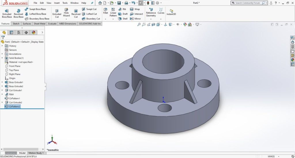
I’ll explain how to use SolidWorks by creating a 3D part model of a simple flange. We’re going to create the flange shown below.
I hope this article is useful for your designs and drawings in future!
- 1 1. What kind of software is SolidWorks?
- 2 2. SolidWorks pricing
- 3 3. Features of SolidWorks
- 4 4. Create a new file
- 5 5. Create a circle using the sketch command
- 6 6. Extrude the sketch to create a 3D model
- 7 7. Create a boss on a top surface
- 8 8. Create a through-hole
- 9 9. Create a rib
- 10 10. Make a circular pattern of the rib
- 11 11. Dimension a sketch
- 12 12. Create a drawing
- 13 13. Summary
1. What kind of software is SolidWorks?
SolidWorks is a 3D CAD software program for machine design released by Dassault Systemes in France.
SolidWorks is one of the most popular and widely used 3D CAD software programs, with a large installed base (5.6 million users worldwide as of October 2018).
It is used for design in a broad range of industries, including industrial equipment, medical devices, architecture and factory design.
2. SolidWorks pricing
The price of SolidWorks (as of August 2019) is JPY985,000 to JPY1,580,000, depending on the desired functionality.

For more details, go to the official websit.
3. Features of SolidWorks
Solidworks has a wide range of features such as sheet metal, welding, moulding, data conversion and animation, along with plenty of additional options developed by other vendors. This makes it very versatile and suitable for use in many different industries.
It also has CAM features up to 2.5D.
4. Create a new file
OK then, let’s get started!
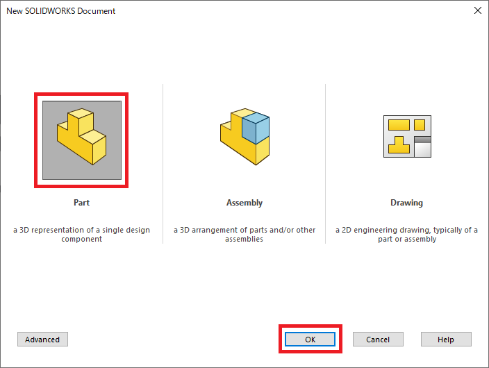
Click [File] then [New]. Select [Part] from file types to create the file, and click [OK].
5. Create a circle using the sketch command
Once you have created the file, create a sketch to make a profile.
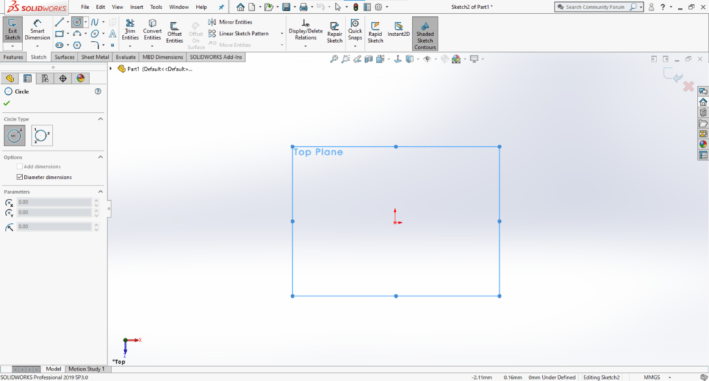
When creating a sketch, you need to specify the surface you are working on.
In this example, I want to create a sketch on the top plane, so choose [Top Plane] from the Tree on the left side of the screen.
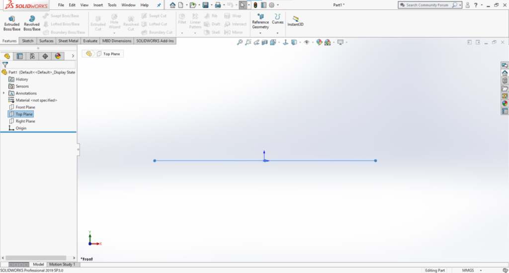
Next, select the [Sketch] tab under the menu and then select [Circle].
Now we are going to create a circle.
First, click the point that will be at the center of the circle, and then click a point of your choice to provisionally determine the size of the circle.
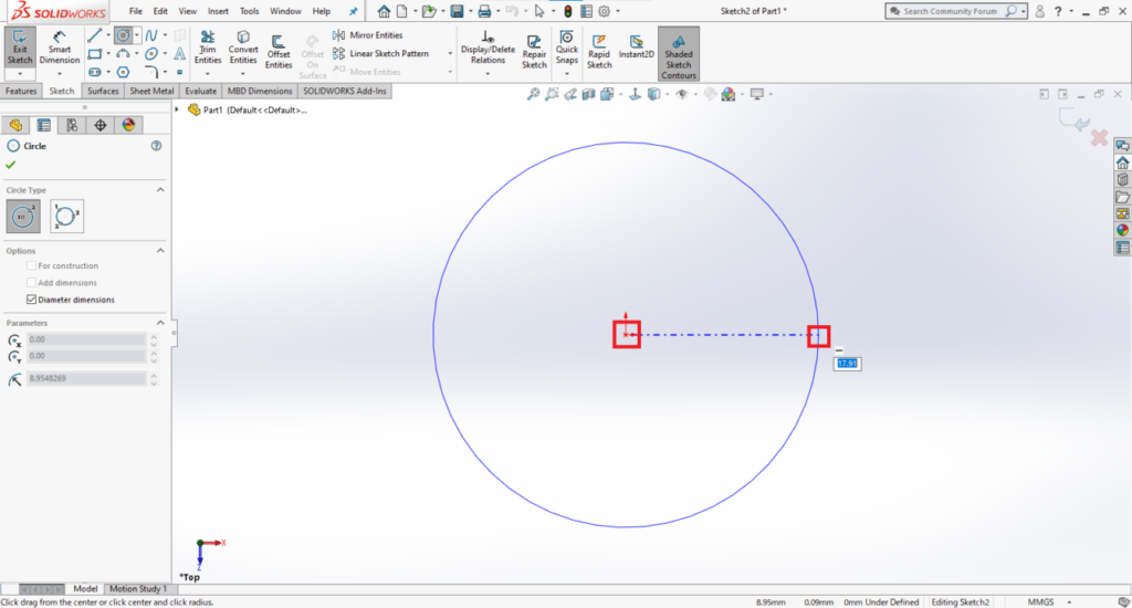
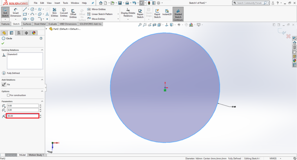
Next, set the size of the circle using [Properties] on the left side of the screen.
Enter “80mm” for the radius.
6. Extrude the sketch to create a 3D model
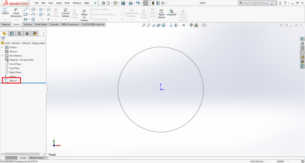
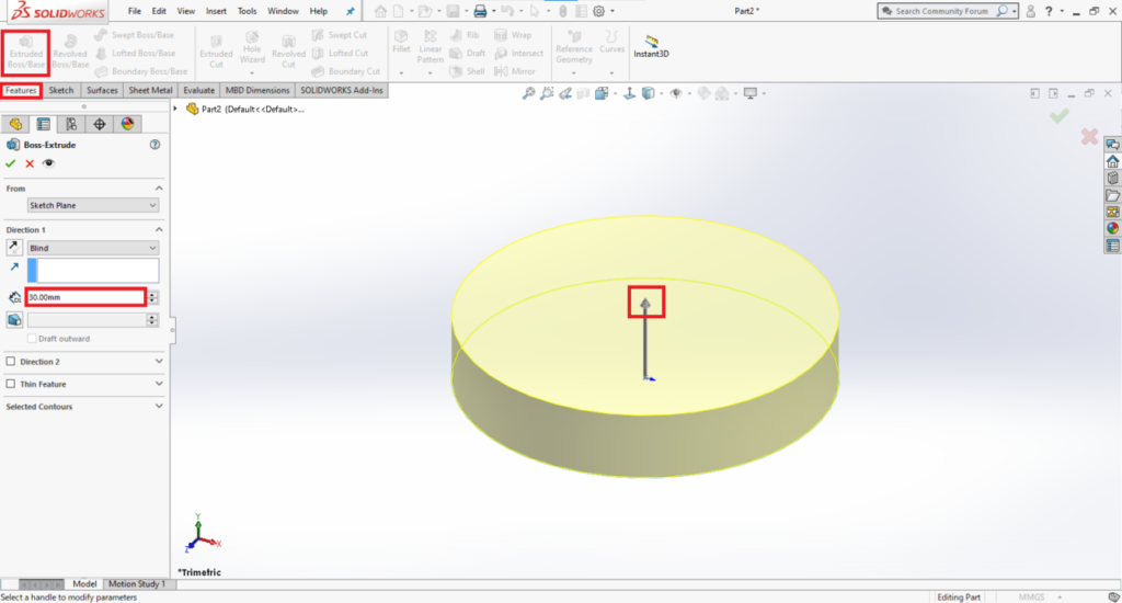
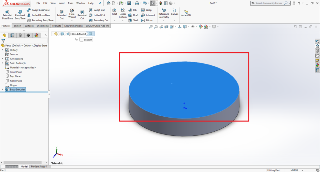
Now we will extrude the circle and make it a 3D solid model.
Click the Sketch in the Tree on the left side of the screen.
Click [Feature] then [Extrude] and drag the arrow upwards. A preview image will be shown. Set the height to 30 mm.
7. Create a boss on a top surface
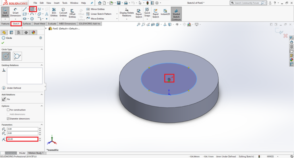
Next, we will create a boss on the top surface of the cylinder we created earlier.
First, create a sketch for the profile of the boss.
Click on the top surface of the cylinder since we need to specify the surface we are making the new sketch on.
After this, we do the same as before.
Click [Sketch] then [Circle]. Click the center of the cylinder to set the center point of the new circle and then set its diameter.
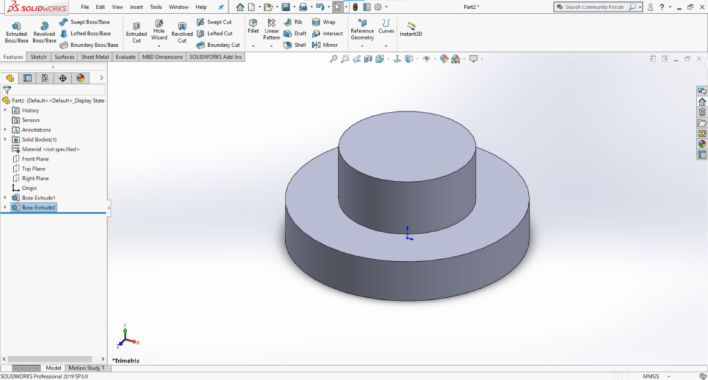
We now create a boss based on the new circle.
Choose the circle from the Tree and click [Features] then [Extrude] to create a boss 40mm high.
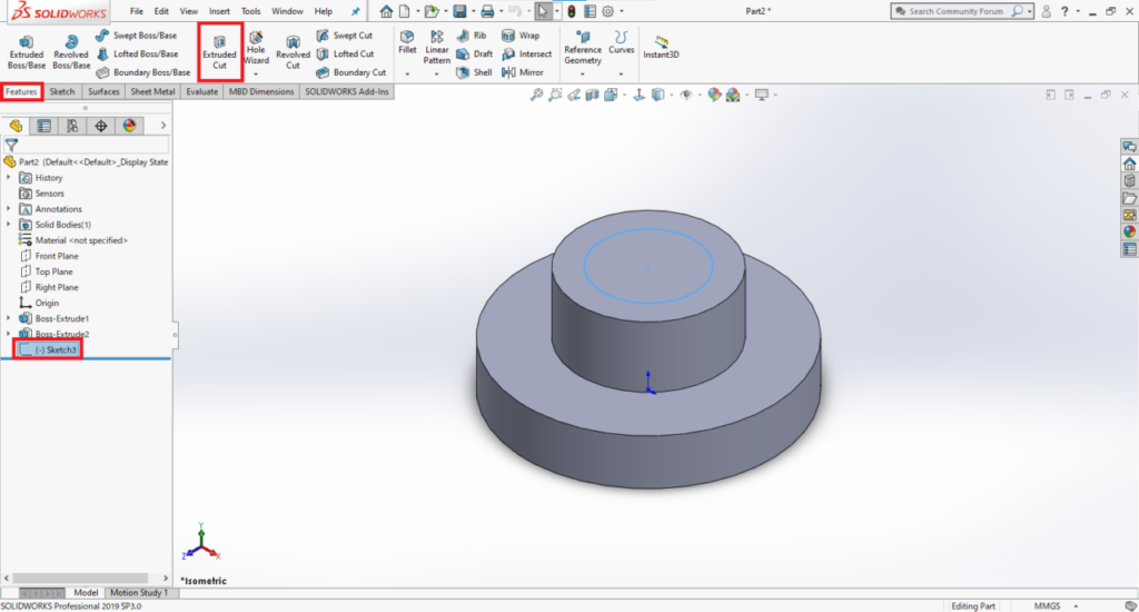
8. Create a through-hole
We now create a hole on top of the boss.
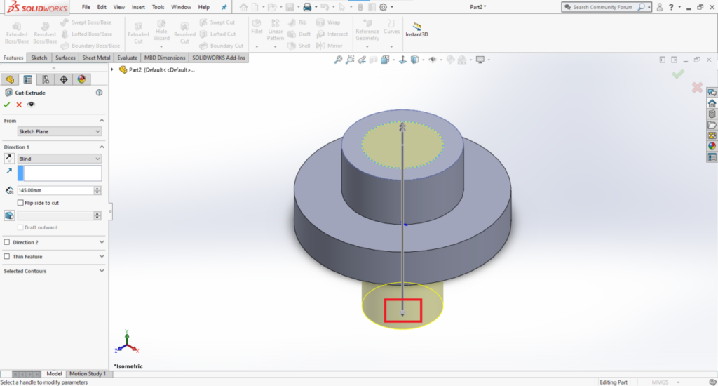
In the same way as for creating a boss, create a sketch for the profile of the hole, and click [Features] then [Extruded Cut].
Drag the arrow down far enough to penetrate the cylinder.
9. Create a rib
We now create a rib for reinforcement.
We do this by making a profile using the Line command.
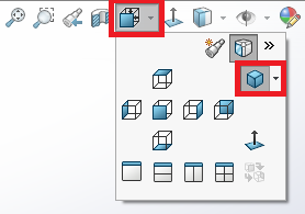
We create a sketch on the front plane this time. Select [Front Plane] in the Tree.
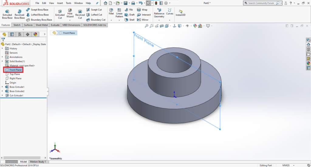
This view will make sketching on the front plane easier.
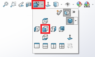
There is also a setting which automatically switches views when creating a sketch.
Check out our earlier article “Introducing optional settings to make it easier to create sketches in SOLIDWORKS” for more information.
Select [Sketch] then [Line]. Click two points to create a line as shown below.
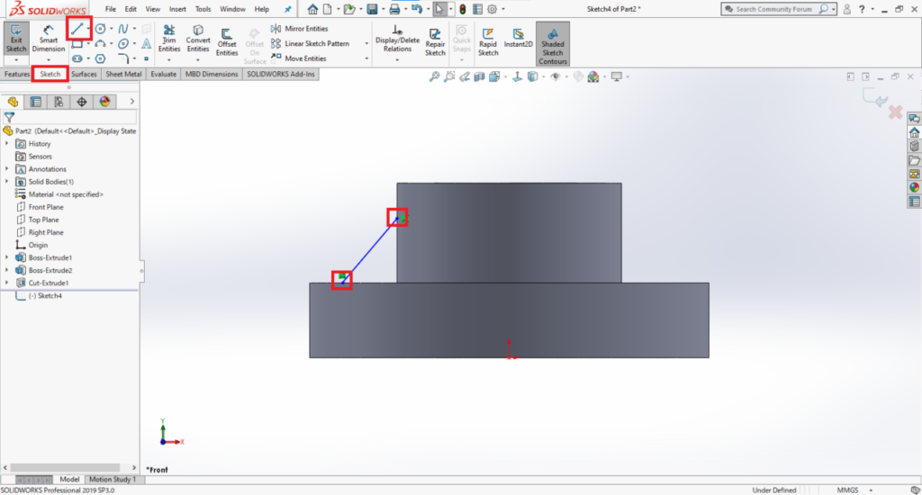
Once you have finished the sketch, go back to the previous view.
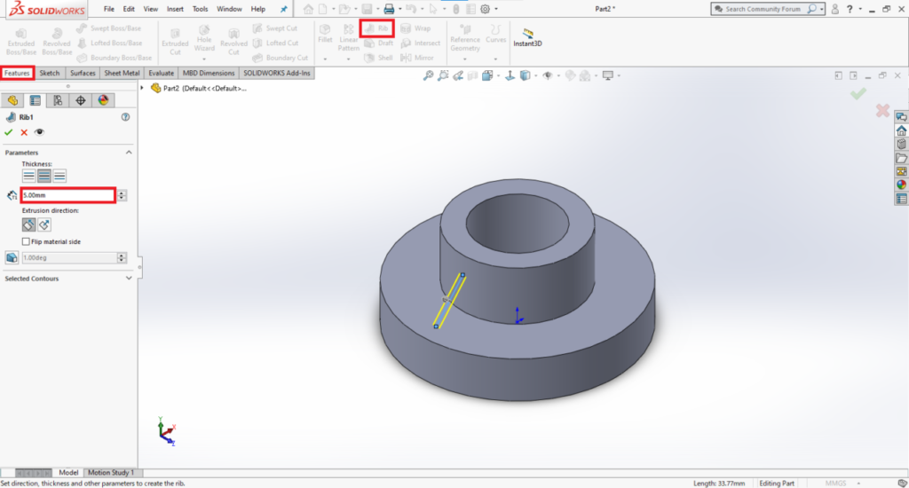
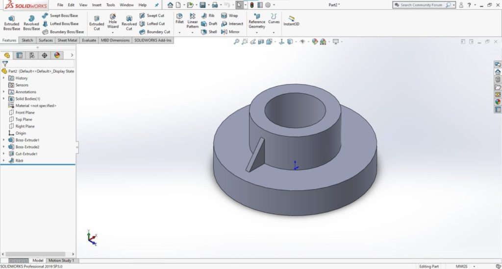
Select [Features] then [Rib] and set the thickness to 5mm to create a rib.
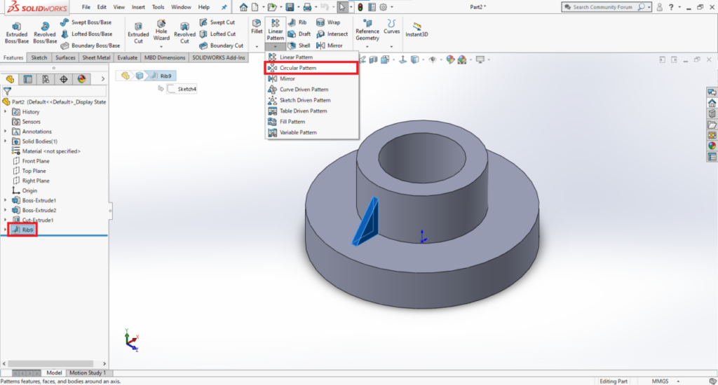
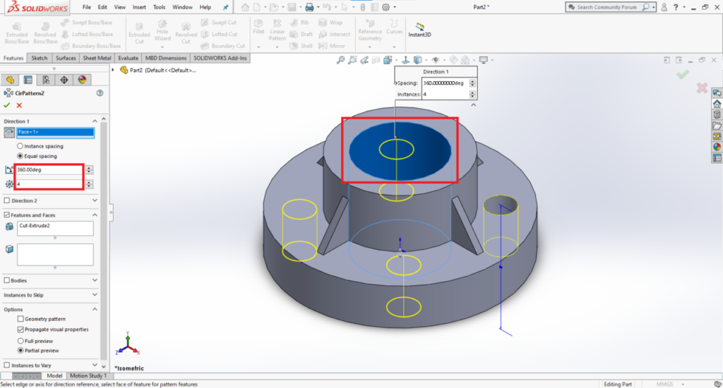
10. Make a circular pattern of the rib
You can choose to create three more ribs in the remaining three places respectively, but I will show you a more efficient way of reproducing the rib around the circle.
Select [Features] then [Circular Pattern].
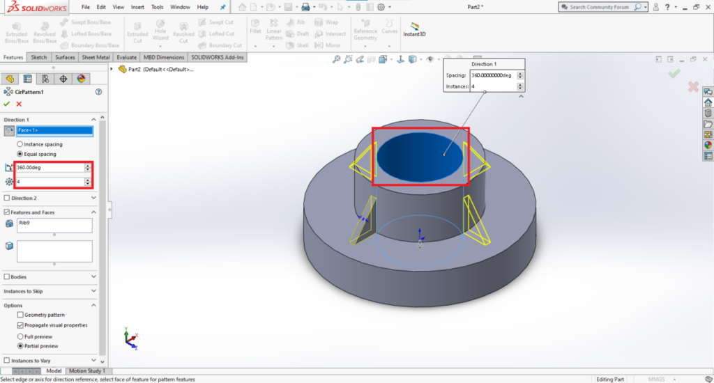
Choose the top of the through-hole to specify the rotation axis and check [Equal Spacing].
Set the angle to “360” and the number to “4”.
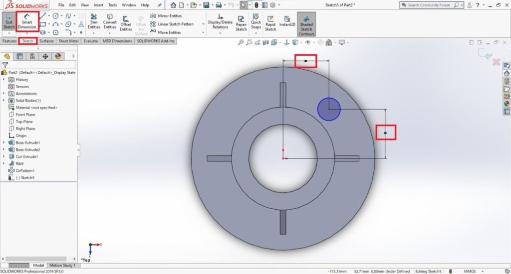
11. Dimension a sketch
We are going to make a through-hole to complete the flange.
First, draw a circle by clicking [Sketch] then [Circle] at a position of your choice.
After creating the circle, select [Sketch] then [Smart Dimensions]. Click the origin point and the center of the circle. By setting the dimensions as shown below, we can set the position of the circle.
Select [Features] then [Extruded Cut] to make a through- hole.
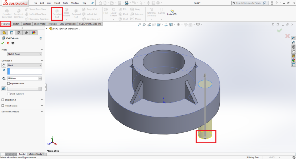
After that, copy the hole by clicking [Features] and [Circular Pattern]. Then your flange is finished.
12. Create a drawing
Finally, we make a 2D drawing of the 3D model of the flange we created earlier.
First, name the 3D model file and save it.
Then click [File], [New] and [Drawing].
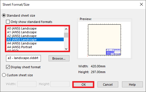
Choose a sheet size and click [OK].
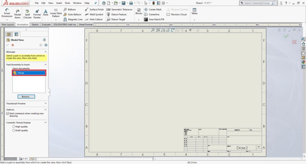
Click [Browse] and choose the file you have just saved (3D solid part model of the flange).
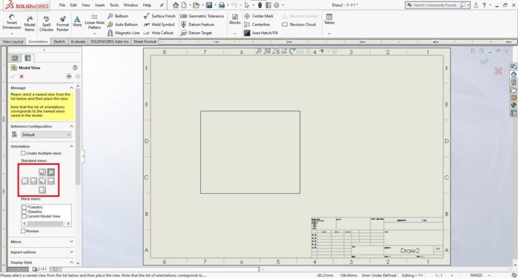
Choose the display direction and click the drawing sheet to set it.
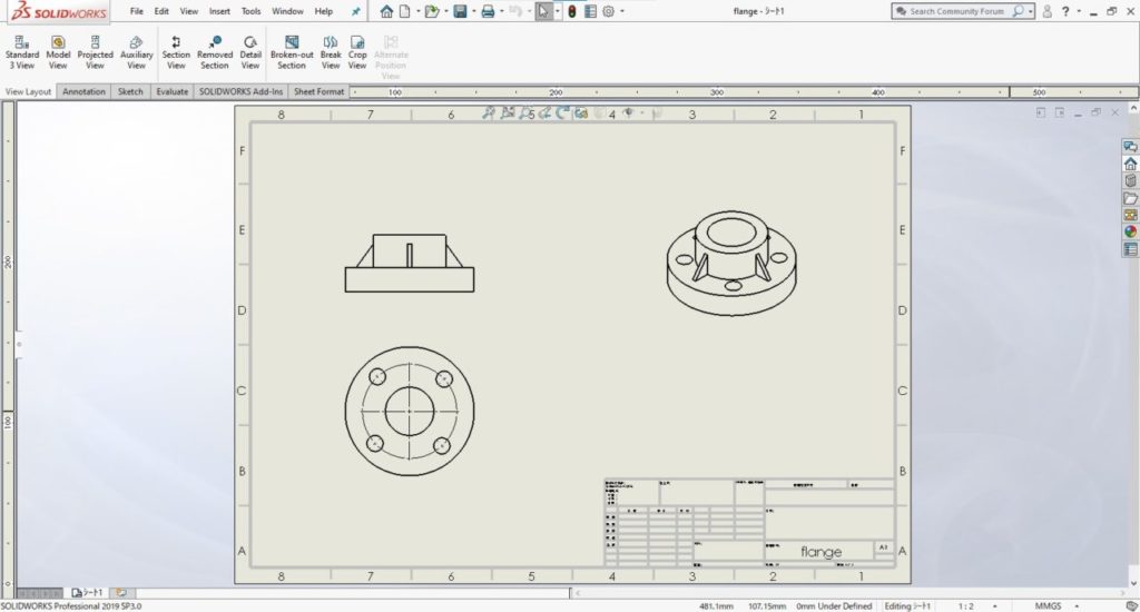
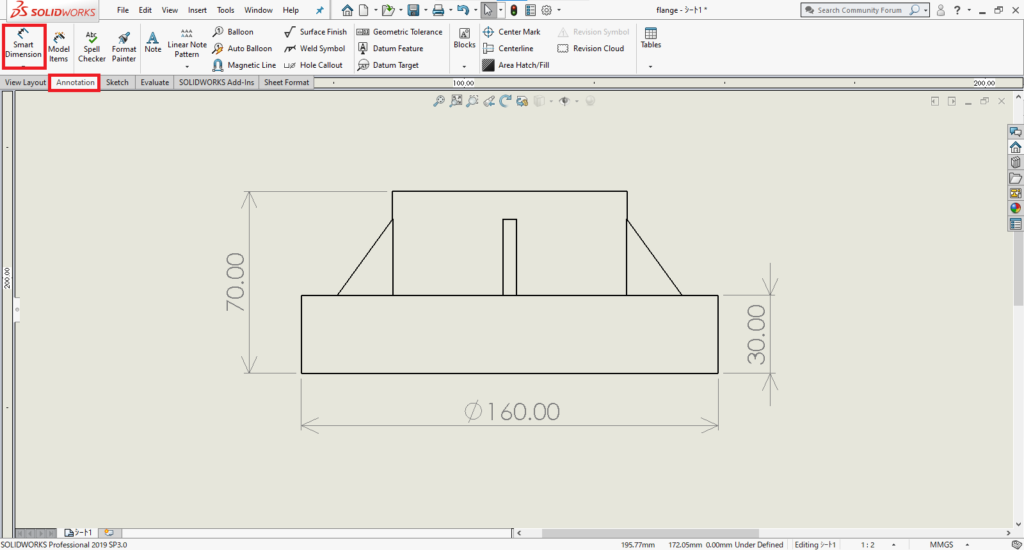
Finally, set the dimensions by clicking [Annotation] then [Smart Dimension].
For those who want to master SolidWorks and use it at work, I recommend the “SolidWorks Master Course,” which teaches you the main operations for SolidWorks operations over two days.
This course is designed to give you the skills to use SolidWorks at work, based on actual work flows.
I recommend this course because it gives you a comprehensive overview of the commands required for your work such as design changes, assemblies and drawing creations.
Click here for more details on the SolidWorks Master Course.
13. Summary
In this article, I’ve explained the basic operations for designing and creating drawings using SolidWorks.
SolidWorks 3D CAD software has many features and is widely used in the design and manufacturing fields.
By understanding its basic features and how to use them, you can expand the range of manufacturing method options available to you.
We have many other articles on design methods using SolidWorks and other features of the software. Feel free to take a look at these too!