CAD and CAM software have become allies to a variety of professionals and students by simplifying and automating the design process. These tools allow engineers, architects, and designers bring to life their projects through the use of technology with high fidelity. In this sense, there are many software and platforms available, and Fusion 360 is one of the most popular.
- 1 What is Fusion 360?
- 2 What is Fusion 360 used for?
- 3 Advantages and drawbacks of Fusion 360
- 4 Useful knowledge for using Fusion360
- 5 How to start using with Fusion360
- 6 Create a component
- 7 Measuring and checking dimensions
- 8 Exporting files in Fusion 360
- 9 You can design with Fusion 360 right away by following the steps
What is Fusion 360?
Fusion 360 is a CAD/CAM/CAE cloud-based software developed by the software design company Autodesk. This software combines easy and dynamic modeling options with high versatility to create manufacturable designs, prototypes, and solids. It also provides simulation and CAM options that makes Fusion 360 unique in the computerized design market.
Visibility of objects
Users can activate or deactivate the visibility of features or components, which makes the task of editing a lot easier by simplifying drawings temporarily.
You can also make objects visible when you want to insert parts into an assembly or use components to create new parts in the same assembly.
What is Fusion 360 used for?
Fusion 360 provides a variety of options in the product development process, including 3D modeling (design), rendering, manufacturing, 2D drawing, and CAM toolpath generation for CNC machines.
It is used to store designs and share them with collaborators, and since the design is stored in the cloud, it allows users to iterate, modify and edit in real time.
At the same time, Fusion 360 is used to create professional, high-quality renderings and animations with an incredible interface.
A unique feature of Fusion 360 is its integrated CAD/CAM environment and its specific tools for 3D printing, making this software the first option for beginners and enthusiasts of the 3D printing technology.
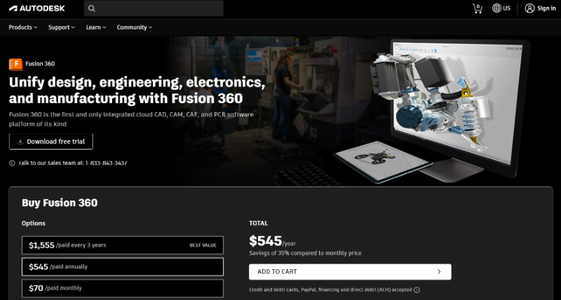
Advantages and drawbacks of Fusion 360
We will explain what are the advantages and disadvantages of Fusion 360.
Advantages
- The software offers realistic renders and animations with high-definition and professional outcomes
- It’s easy to learn for beginners, it contains more condensed commands than other CAD/CAM software. It’s more visually dynamic.
- It allows users to edit, modify and create in the Cloud, making it the number one choice when working with teams on design projects.
- It is versatile in terms of operating systems (compatible with Windows and MAC) and provides many file conversion options for third-party software.
- It helps the manufacturing process by integrating STL and STEP files. Also, it is the only Autodesk software integrated with a 3D printing section.
Drawbacks
- The software needs high-speed internet to work properly since it’s cloud-based. The offline option is available, but it’s restrictive since you would need to be online to share files.
- Users can’t customize keyboard shortcut keys when using Fusion 360.
- It’s advisable to have a graphics card to obtain high-quality designs in Fusion 360 and guarantee the proper functioning of the software. Otherwise, the screen can tend to freeze.
Useful knowledge for using Fusion360
Here we will explain the knowledge that can be used to use Fusion 360.
Joints
A Join is a constraint defined by the user to restrict how components move in an assembly. They are created between components and defined by specific features in them, like faces, bodies, or edges.
Rigid Groups
Instead of creating multiple Rigid Joints, you can create a Rigid Group to constrain multiple bodies to each other, with no movement relative to one other. The Rigid Group function locks the relative position of the selected components. When you move or apply joints to the components, they act as a single object.
Shortcut list
| Ctrl+Shift + F | Full-screen |
| Delete | delete selected object |
| Shift + Middle Mouse Button | orbit |
| Crtl + Z | undo |
| Crtl + C | Copy |
| Crtl + V | Paste |
| Crtl + X | Cut |
| S | Sketch Toolbox |
| R | 2-point rectangle |
| C | center diameter circle |
| E | Extrude |
| F | Fillet |
| H | Hole |
| J | Join |
| L | Line |
| I | Measure |
| M | Move |
| O | Offset |
| P | Project |
| D | Sketch dimension |
| T | trim |
| Crtl + A | All CAM tools |
| Crtl + I | Import Tool Library |
| Crtl + E | Export Tool Library |
| Crtl + G | Generate Toolpath |
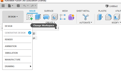
How to start using with Fusion360
First-time users may not know how to start designing. I will explain the steps here.
Create a new project
- Enter the Data panel and click on New Project
- Click on the File icon and select New Design or type Ctrl+N.
Start sketching
- Choose one of the planes from the coordinate system for manufacturing purposes. It is advisable to choose the XY plane.
- Choose the option <<Create>> from the Top menu or Toolbar set by Default in the program and then click on the option <<Create Sketch>>
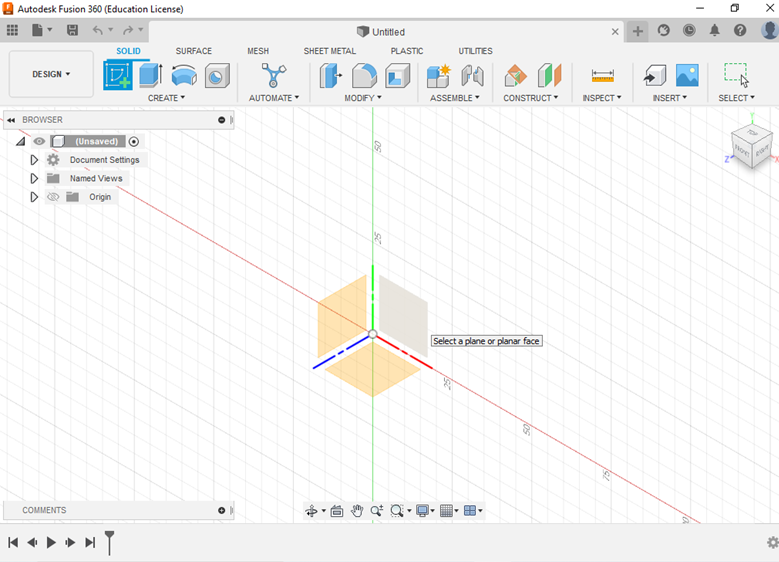
- Select a plane or planar face to start the Sketch.
- Search for the shape you want to use. For example: center rectangle, line, center point arc, center diameter circle, etc.
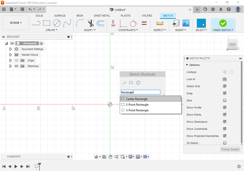
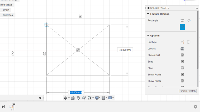
- Choose the shape from the menu and then place the cursor in the origin.
- Click on the coordinate origin and assign the dimensions of the chosen shape. For example: the length and width of a rectangle.
Starting operations in the 3D environment
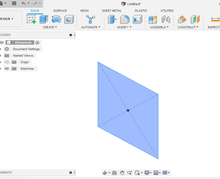
- When you are done drawing the 2D shapes (e.g. circles, arcs, rectangles), you would see closed shapes highlighted in pale blue and open figures without any shadow. This is helpful when creating sketches to identify closed figures before entering the 3D environment.
- Click on <<Finish Sketch>> located on the right side of the top toolbar.
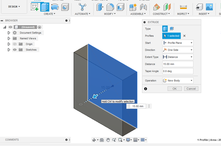
- Now you can decide what operation you want to do next to create a 3D object. You can choose the operation type by clicking on <<Create>> in the top toolbar and a list of options will appear: Extrude, revolve, sweep, loft, emboss, etc. You can also use the key shortcuts to choose one of these options.
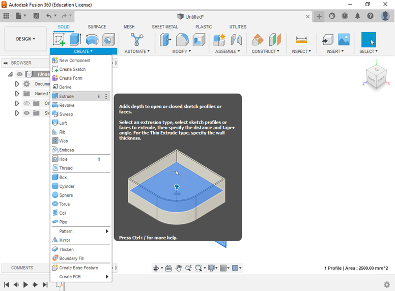
- Click the operation you want to use or use the appropriate shortcut and the program will automatically ask you to type in the length of the new dimension. After you enter it click ENTER to complete the operation or click <<OK>>.
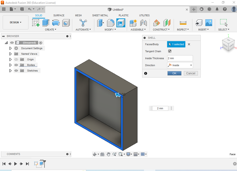
- You can also modify the qualities of an object or drawing by clicking on <<MODIFY>> on the Top Toolbar and choosing one of the following options: filet, chamfer, scale, combine, offset, draft, split, etc. Or you can use the shortcuts for one of those options.
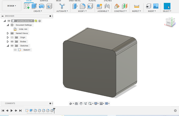
Create a component
There are several ways to create components:
1. Creating a component after a 3D operation
- Once you complete a 2D sketch, you can select a 3D operation (Revolve, extrude, emboss, rib, etc.), and a dialogue box will pop up with the details of the feature such as dimension, direction, properties, taper angle, and operation.
- Click on <<Operation>> in the newly displayed menu and the option <<New Component>> will appear.
- Once the component is created you can change its name by simply clicking twice on the “component 1” name and typing its new name.
2. New component below the browse bar by right-clicking on Unsaved option
- Activate the new component by clicking the blank circle placed next to the component name
- Change the component name to maintain order in your drawing. For example “Box 1”.
- Click on the down menu next to the new component (triangle shape on the left) to find the <<Origin>> option. A 3D coordinate system will appear on the screen to choose the plane you want to start working on.
Measuring and checking dimensions
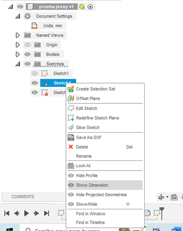
- To display the dimensions for a sketch, right-click on the sketch located in the browser. Then, left-click on Show Dimension. You can also use the D shortcut.
- You can change or modify the dimensions by clicking on the text box where the dimension appears.
- Repeat this process with as many objects or planes as you need by looking for them in the browser menu.
- In the 3d environment, you can see the object’s dimensions and other physical aspects such as area and volume by clicking in the INSPECT menu on the option MEASURE. This option is also valid when working on the 2d sketch environment.
Exporting files in Fusion 360
When users want to export their files to other software or save their files in a different format, they have many available options. Fusion 360 allows saving complete projects as well as partial ones, including bodies or components, depending on the user’s need. There’s also a variety of options in terms of file types, these are:
File Types
If you want to work with Non-Native files (formats that do not belong to Fusion 360), including files that are not generated in any Autodesk software, you´ll find many options. Some of the most popular file types to work in this case are:
- STEP: The Standard for Exchange of Product Data is governed by ISO standards and it specializes in engineering disciplines.
- DXF: Drawing Exchange Format (DXF) is the AutoCAD file by default which is supported in the 2D environment. You can directly export Sketches to this format by a simple right click.
- STL: The Standard Tessellation Language (STL) file format is widely used in 3D printing, scanning, and some CAM applications. You can directly export Bodies and Components to this format by a simple right click.
- IGES: Initial Graphics Exchange Specification, is the CAD format that preceded the STEP format, it includes graphical data but not all the solid modeling information.
If you want to work with Native files (formats that belong to Fusion 360), you´ll find two options:
- F3D: it is the default file type for a single design, including single or multiple components.
- F3Z: is a file type used for distributed designs, that include externally referenced F3D files
Save a file as Mesh
This option is useful to export or save an entire project as well as individual bodies or components. To achieve this, you should follow these guidelines:
1.- Right-click on the top where the project name is and select “Save As Mesh” in the drop-down menu that will appear on your screen.
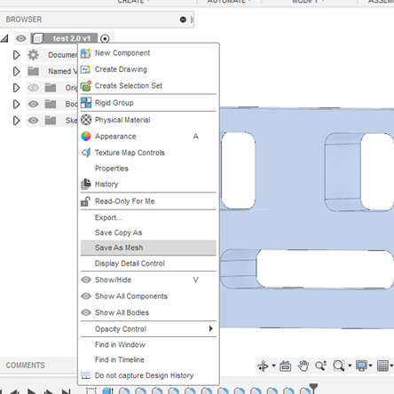
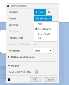
2.- Once you select the “SAVE AS MESH” option a panel will appear on the right side of the screen. This panel allows users to configure Mesh exporting options including format, refinement and Units.
Exporting a single body or component as Mesh
1. Right-click the body or component in the Browser tree, and select “Save As Mesh” in the resulting menu.
2. The “SAVE AS MESH” panel will appear just like the previous method, to configure your mesh settings.
Exporting to a 3D Printing Format
There are basically three available options for users to export to a 3D format (STL). The first 2 ways are exactly like the methods used to SAVE AS MESH, but when the mesh panel appears, you can click on the “Send to 3D Print Utility”.
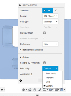
This time, when clicking this option, it will display a resulting menu in Print Utility to choose the third-party program you want to work with for the 3D modeling (Cura, Print Studio, Preform, Meshmixer).
If you just want to export the project to an STL format, leave the “Send to 3D Print Utility” unchecked and click on the “OK” button in the “SAVE AS MESH” window. Make sure that the format selected is <<STL(Binary)>> in the Format options at the Mesh panel.
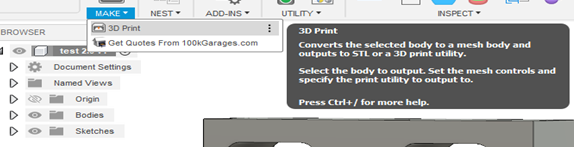
The last option available is using the 3D printing command in which you can follow these guidelines:
1. Navigate to the Tools tab in the toolbar.
2. Click on 3D Print from the <<Make>> menu located in <<UTILITIES>>.
3. Select the bodies you want to export to STL format by clicking on <<selection>> first. The selected bodies will be highlighted in blue.
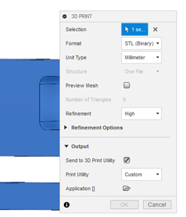
4. Leave the <<Send to 3D Print Utility>> blank by clicking on it.
5. Then click <<OK>> making sure that all the format settings are correct.
Design History Timeline
The designing timeline is a very useful tool in Fusion 360, and it’s located at the bottom of the screen. It allows users to check, modify and control the design history while working on a drawing. Users can watch the progress of their designs dynamically, and edit or suppress features in intermediate steps of the sketch both in the 2D and 3D environment. This saves users a lot of time in the editing process and makes this software highly versatile.
To Edit any feature in the drawing, you need to right-click on one of the icons in the Design History Timeline and click on <<Edit>>. This will take you to that specific part of the drawing and modify it without affecting the rest of the drawing.
The basics covered in this article mainly focused on the DESIGN environment of Fusion 360, however, this software offers many other useful tools to create Renders, Animation, Simulation, and Manufacturing to provide users with a complete experience. Those environments are intended for more experienced designers and will be covered in a different article.
You can design with Fusion 360 right away by following the steps
Please follow these steps to start Fusion 360 and start using 3DCAD.
Fusion 360 has an easy-to-understand interface, so even beginners will find it easy to use.