
AutoCAD has emerged as an indispensable tool for 2D designers and engineers, with the capability to easily transform drawings into the three-dimensional realm. However, the true potential of its powerful features can only be realized with a proficient grasp of its commands and operations. This article offers a comprehensive guide on how to effectively utilize AutoCAD, from the initial setup to executing commands and implementing techniques that can help you create more accurate drawings and showcase your creativity. Keep reading to unleash your design potential with AutoCAD!
Downloading and Installing AutoCAD
First, install AutoCAD on your computer.
How to Install AutoCAD
Check the system requirements to ensure compatibility with AutoCAD. These requirements may vary depending on the version, which is updated every one to two years. For Autodesk’s latest version of AutoCAD (2023), the following requirements are necessary.
Microsoft Windows Operating System
| Requirement | Minimum | Recommended |
| Operating System | 64-bit Microsoft Windows 10 or Windows 11 | N/A |
| Processor | 2.5–2.9 GHz processor | 3+ GHz processor |
| Memory | 8 GB | 16 GB |
| Disk Space | 10 GB | N/A |
| Display | 1920 x 1080 resolution with True Color
Resolutions up to 3840 x 2160 supported on Windows 10 |
N/A |
| Display Card | 1 GB GPU with 29 GB/s Bandwidth and DirectX 11 compliant | 4 GB GPU with 106 GB/s Bandwidth and DirectX 12 compliant |
Mac Operating System
| Requirement | Minimum | Recommended |
| Operating System | Apple macOS v10.14+ | N/A |
| Model | Mac Pro v4.1 MacBook Pro 5.1 iMac 8.1 Mac mini 3.1 MacBook Air MacBook 5.1 |
Mac models supporting Metal Graphics Engine |
| CPU Type | 64-bit Intel CPU | Intel Core i7 or higher |
| Memory | 4 GB | 8 GB+ |
| Display Resolution | 1280 x 800 display | 2880 x 1800 with Retina Display |
| Disk Space | 4 GB | N/A |
Visit the official Autodesk website for pricing information and to purchase an AutoCAD license.
Standard Installation Process from an Autodesk Account
These instructions, provided by Autodesk’s official website, are intended for new AutoCAD users who want to install the software for the first time.
- If you don’t have an account yet, start the process by signing in to Autodesk and click on “Create account”.
- Sign in to your account at manage.autodesk.com.
- From the “All Products and Services” tab in your account, select a product and download method (refer to Download methods).
- If you choose the Download method, perform the following steps based on your operating system:
- Windows: Run the EXE file
- macOS: Mount the DMG file
- Linux: Extract the TAR file
- Read and accept the license agreement.
- Click on “Install”.
- If a “Product Language” drop-down menu appears, select the preferred language. If the menu is not visible, you can download and install a language pack after the product installation.
- Optionally, you can choose a new installation path if available, instead of the default one.
- Once the installation is complete, either close the installer or start the product.
Note: For more specific or up-to-date instructions, please refer to Autodesk’s official website.
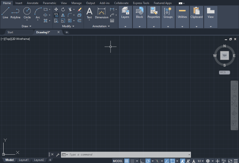
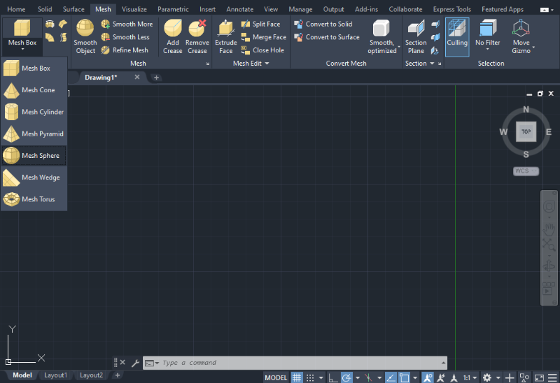
AutoCAD User Interface
Once the program is open, create a new project. Depending on your computer’s capacity, it may take a few minutes for the program to initiate. To start a new project, click on “New” in the left-side panel to access the program’s main working space, where the design process takes place. This new space contains a set of basic tools and features to begin designing. These include a:
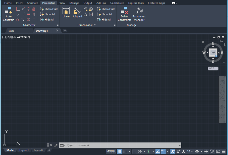
- Quick Access Toolbar: It contains all the basic icons for tasks such as opening, creating, and saving files. The toolbar is easily customizable and can be manipulated as needed.
- Ribbon: It arranges a variety of tools in tabs, providing a compact interface.
- Command Bar: It serves as a search tool for users to find commands by typing them manually. The Command bar lists commands and provides additional tips and information about each.
Setting the Workspace
Let’s set up the AutoCAD screen.
ViewCube
The ViewCube is located in the top-right corner and is set to the top view by default. To change views from different angles, hover your mouse over the icon. In the middle of the drawing space, you will see a coordinate system. Click on faces, edges, or corners to select the desired view.
Navigation Orbit
Navigation Orbit is a tool similar to the ViewCube. It helps control the display of a view. It appears as a round shape and contains cardinal directions to assist with the orientation of the drawing. It also allows users to orbit the drawing space or sketch in a three-dimensional space.
Quick Access Toolbar
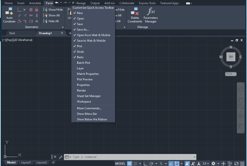
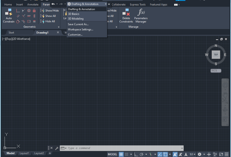
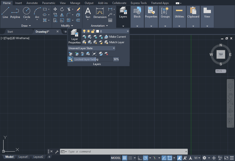
In the Quick Access Toolbar, located at the top next toore to starting the desi the AutoCAD symbol, click on the downward extend arrow to access customization options. A drop-down menu will appear with various choices. One useful tool to add is the Layer icon or the Workspace option, which allows you to switch from Drafting and Annotation to a 3D modeling environment.
By default, the Workspace shows the option “Drafting & Annotation.” However, users can change it to 3D options if needed before to starting the design process.
Setting Units
Type the word “UNITS” in the blank space located in the Command bar at the bottom of the screen. As you start typing, the Units command and a brief description will appear.
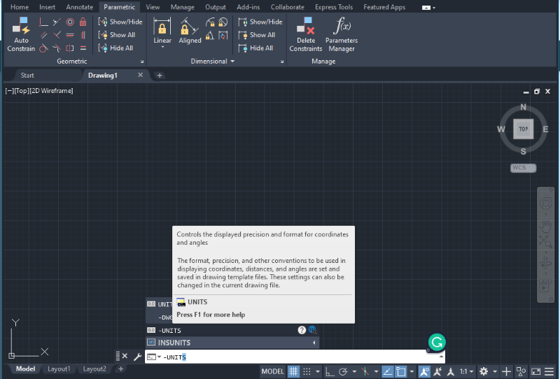
The units you choose won’Ortho Modet affect the creation of objects or the precision of the drawing. However, they will impact the display of length, angles, coordinates, and distances within the program.
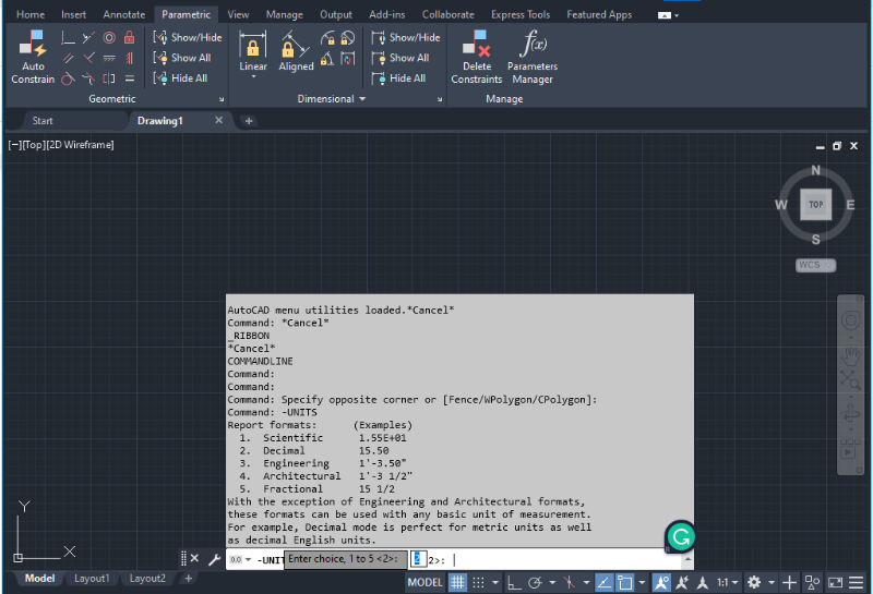
If you prefer working with inches and feet, it’s advisable to select the “Architectural” option (Option 4). If you prefer the metric system, choose the “Decimal” option (Option 2). You can also specify the format in which the dimensions will appear and their precision (the number of decimals displayed). AutoCAD will automatically prompt for this information, and you can use the blinking space in the Command bar to enter the required number of decimals and format.
Object Orientation in AutoCAD
Coordinate Systems in AutoCAD define the reference framework for positioning and orienting objects within the workspace.
Cartesian Coordinates
By default, AutoCAD uses Cartesian Coordinates, where the x-axis represents the horizontal axis (positive to the right and negative to the left), and the y-axis represents the vertical axis (positive upward and negative downward).
Polar Coordinates
This system uses angles and radial distances to represent directions and dimensions in the workspace. In AutoCAD, the angle is measured counterclockwise from the x-axis and is represented using the following format.
- “R” denotes the radial distance
- “<” represents the less than sign, indicating the angle
- “Degrees” indicates the value of the angle in degrees
AutoCAD offers different coordinate modes to restrict object creation and movement within the workspace: Orthogonal (ORTHO) or Polar (POLAR) mode. These options can be found at the bottom of the screen, below the Command bar.
Ortho Mode
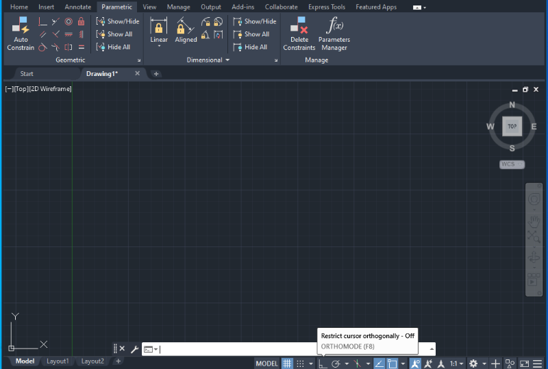
Ortho mode in AutoCAD restricts cursor movement to vertical and horizontal directions relative to the User Coordinate System (UCS). It can be activated using the F8 command.
Polar Mode
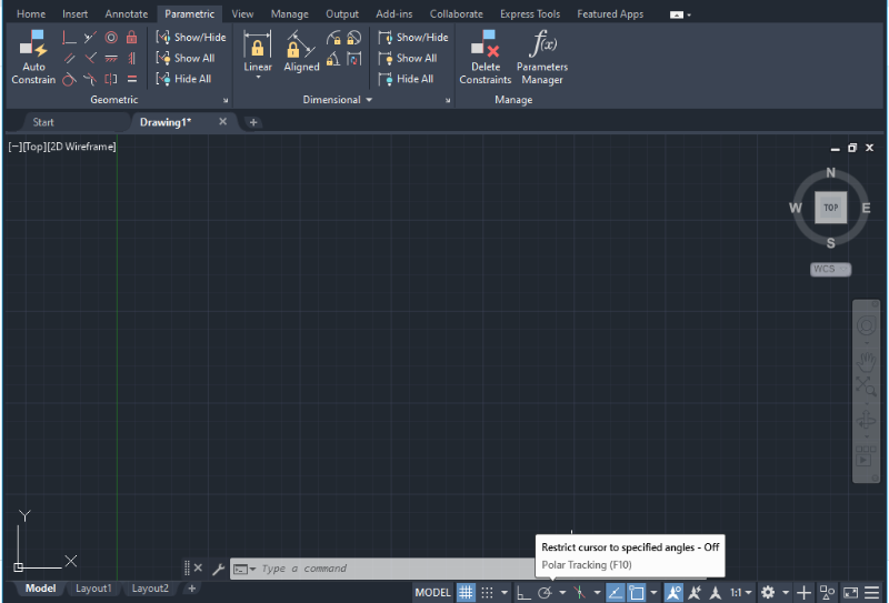
Polar mode or Polar Tracking mode in AutoCAD restricts cursor movement to specific angles and their alignment paths. It can be activated using the F10 command.
How to design with AutoCAD
An easy-to-understand explanation of how to design with AutoCAD.
Line
There are two main options to create lines in AutoCAD.
1. Select the Home tab in the top bar and click on the desired line (Polyline, Line, Arc) displayed in the Draw icons.
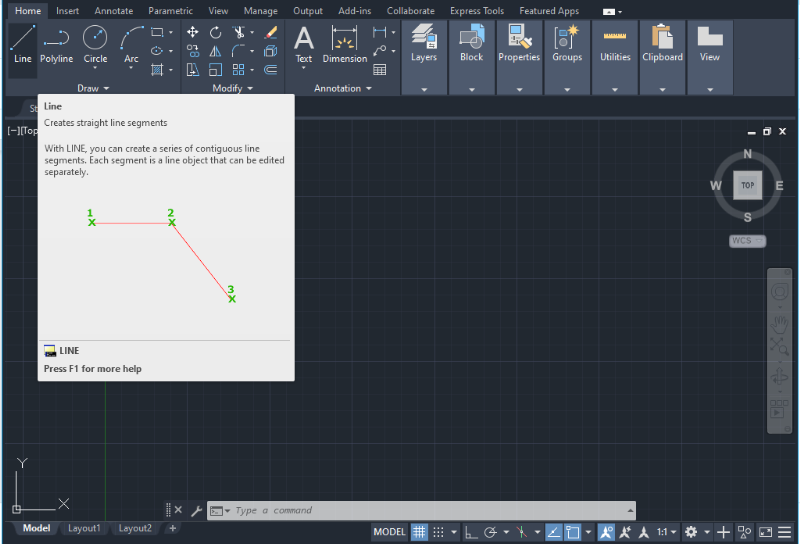
2. Alternatively, type the word “LINE” in the Command bar at the bottom of the screen and click on the displayed menu option “Line”.
In both cases, AutoCAD will provide a dialog box at the bottom of the screen indicating the next possible steps in the design process. The operation of drawing lines will stop only by selecting “Undo” or using the ESC shortcut key.
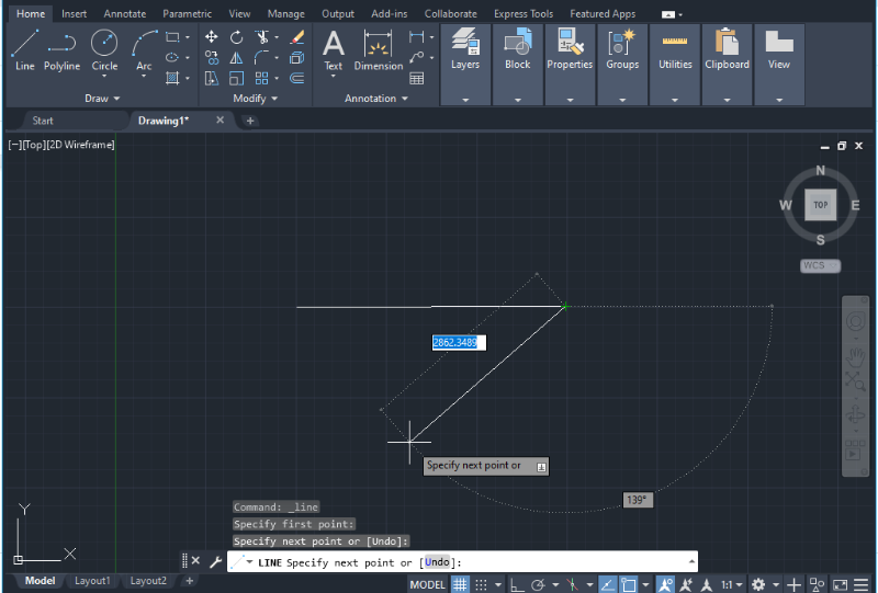
Once you have entered the Line command, the program will ask for the first point of the line. You can either click a random point in the drawing space or enter the coordinates manually. Enter 0 for the X-coordinate, then press the tab key to switch to the Y-coordinate, and enter 0 there as well. Press Enter to confirm, which will select the CenterPoint (0,0) or origin to start your sketch.
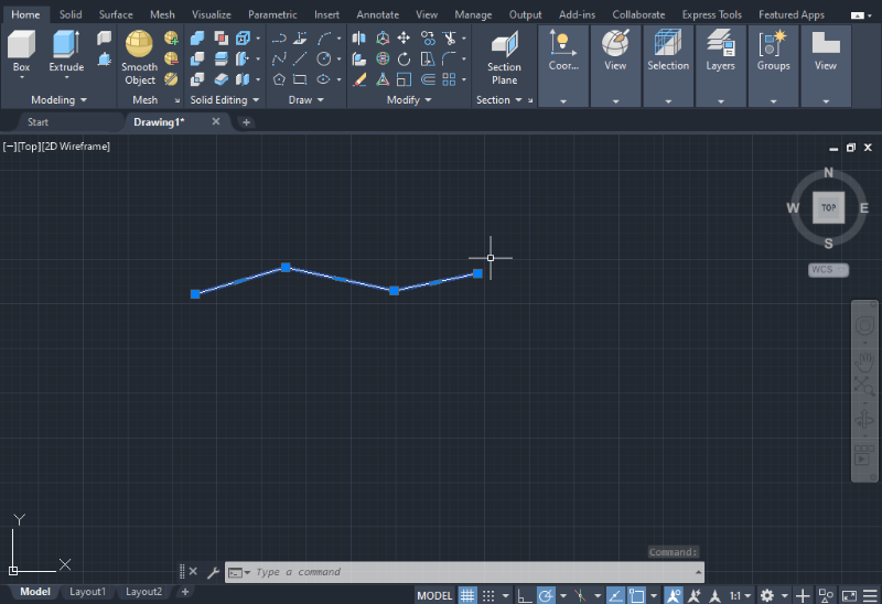
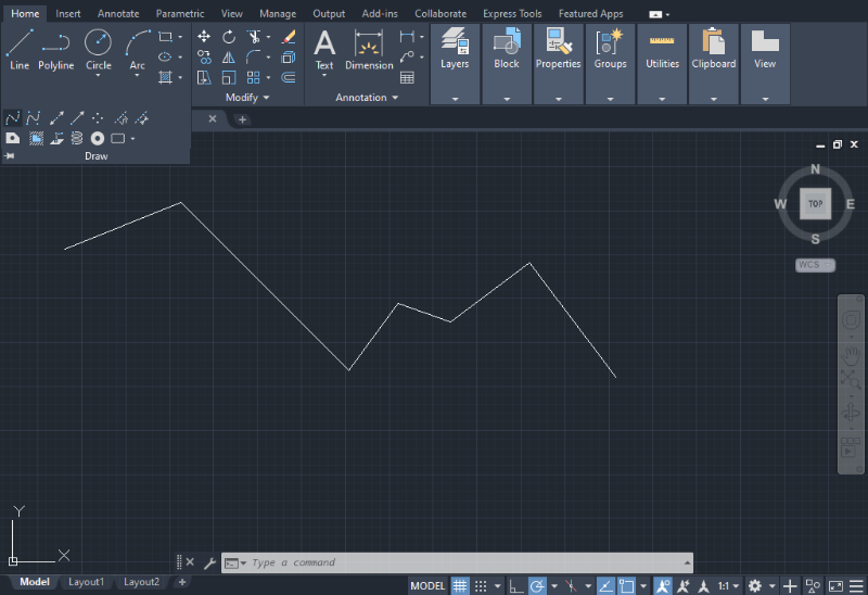
Polyline
1. To draw a polyline you can select the “Polyline” icon located in the Draw section on the Home tab as shown in the image below or type “PLINE” in the Command bar at the bottom of the screen.

2. After selecting the Polyline command, use the mouse to start the line at any coordinate in the workspace and establish the length and angle using the keyboard.
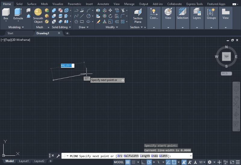
3. By right-clicking again, you will be able to continue to draw the polyline.
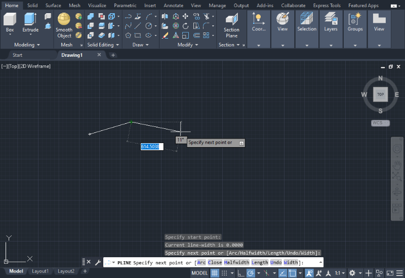
4. When you finish, press Enter to complete the polyline.
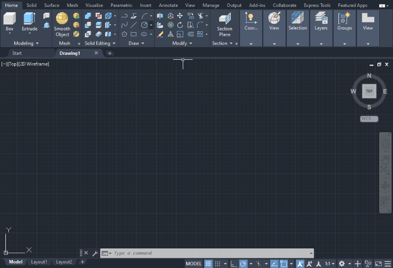
Circle
1. To draw a circle in AutoCAD, you can either select the Circle icon located in the Draw section on the Home tab or type the word “CIRCLE” in the Command bar at the bottom of the screen.
2. There are different options available for creating circles, which you can access by clicking the down arrow below the Circle icon.
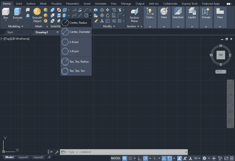
Depending on the option you choose, the program will prompt you to enter the necessary information. For example, if you select “Center, Radius”, the program will ask you to specify the center point for the circle.
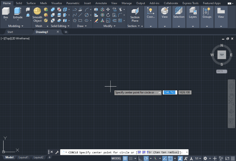
3. After entering the center point, press Enter and enter the radius for the circle.
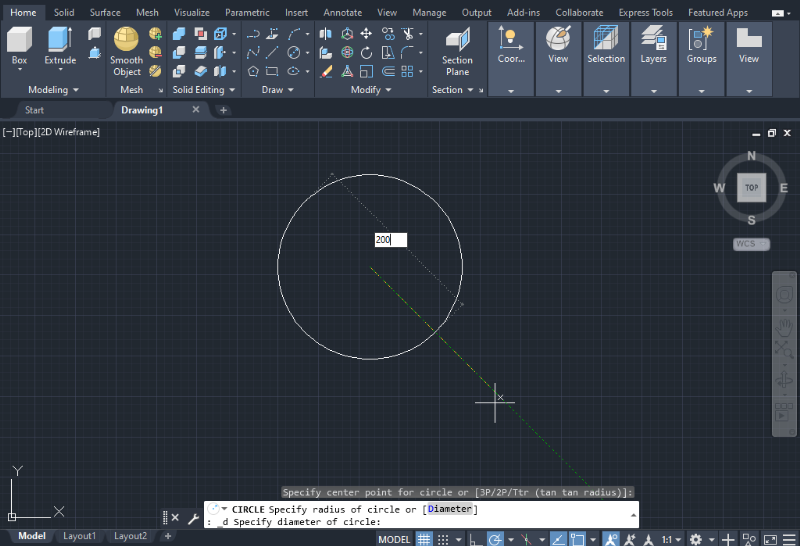
The process for creating circles using other options is similar to the one described above.
Arc
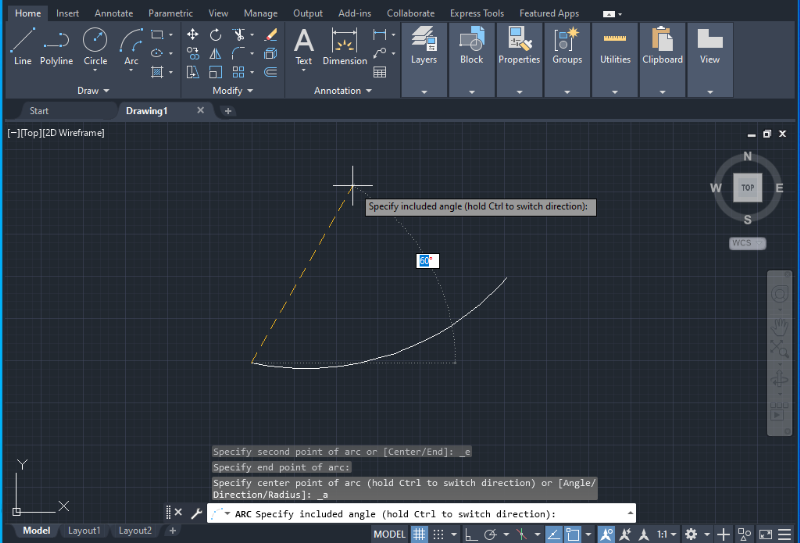
Creating arcs in AutoCAD is similar to creating straight lines, and the program offers various options for constructing the arc, such as using three points, Start-Center-End, or Start-Center-Angle, depending on the available information (dimensions, angles, or radii) during the sketching process.
Depending on the chosen arc type, AutoCAD will prompt you to enter the starting point coordinates or select it with the cursor, followed by inputs for the arc’s length, angle, ending point, or length. After entering the required information at each step, press Enter and follow the on-screen instructions to complete the arc.
Rectangle and Polygon
To easily draw any shape, click the drop-down menu next to the Rectangle shape in the top bar. You can select either a rectangle or a polygon.
Rectangle
1. For creating a rectangle, AutoCAD will prompt you to specify or type the location of the first point for the rectangle, as shown in the image below.
2. Follow the instructions to indicate the next coordinate for the second point, which determines the length and width of the rectangle.
Polygon
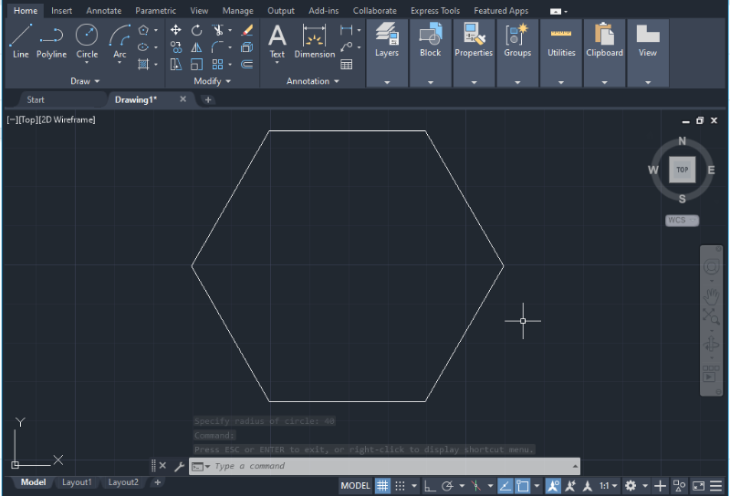
1. For creating a Polygon, AutoCAD will prompt you to enter the number of sides (defaulting to 4). After entering this information, press Enter.
2. Then, specify the center of the polygon or its coordinates and press Enter.
3. Finally, choose between the options “Inscribed in circle” or “Circumscribed in circle”. After selecting the desired option, press Enter and enter the circle radius for circumscribed or inscribed polygons. Users often choose the inscribed option set by default.
You can also use a shortcut key or Command bar to insert a polygon and follow the same instructions to provide the dimensions.
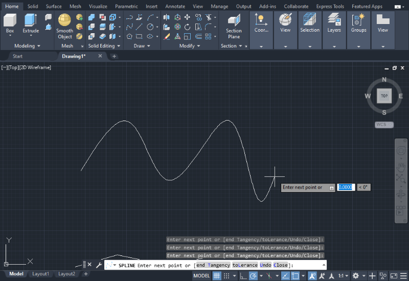
Spline
1. To create a smooth curve or spline, select the Spline icon located in the Draw section on the Home tab and click the drop-down arrow to reveal all the drawing tools (as shown in the image below). Alternatively, you can type the word “SPLINE” in the Command bar at the bottom of the screen.
The Spline command functions similarly to the Polyline command, but it allows you to draw smooth curves instead of straight lines.
2. After selecting the Spline command, click any point in the workspace to start drawing and use the keyboard to establish the distance and angle, as shown in the image below.
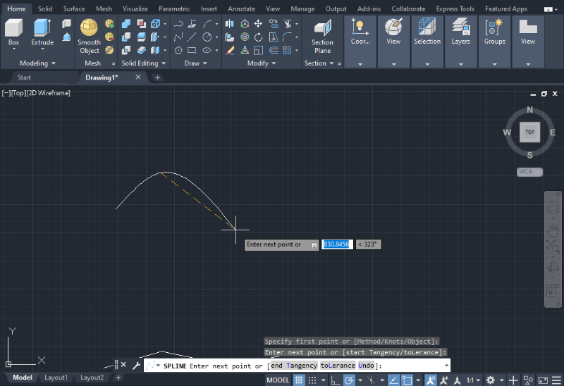
3. To continue drawing the spline, right-click and repeat the previous step.
4. When you have finish drawing the spline, press Enter to complete the operation.
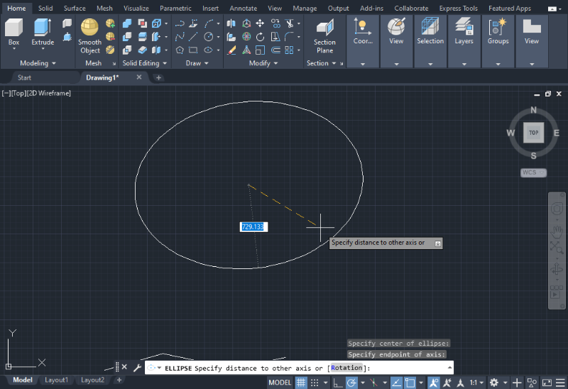
Ellipse
1. To draw an Ellipse, you can select the Ellipse icon located in the Draw section on the Home tab, as shown in the image below, or you can type “ELLIPSE” in the Command bar at the bottom of the screen.
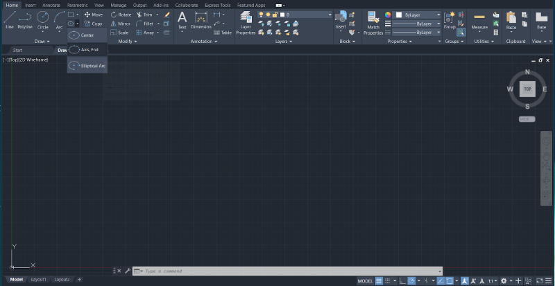
There are different methods to create an ellipse. By clicking the down arrow below the Ellipse icon you will see the available options: Center, Axis, End, and Elliptical Arc.
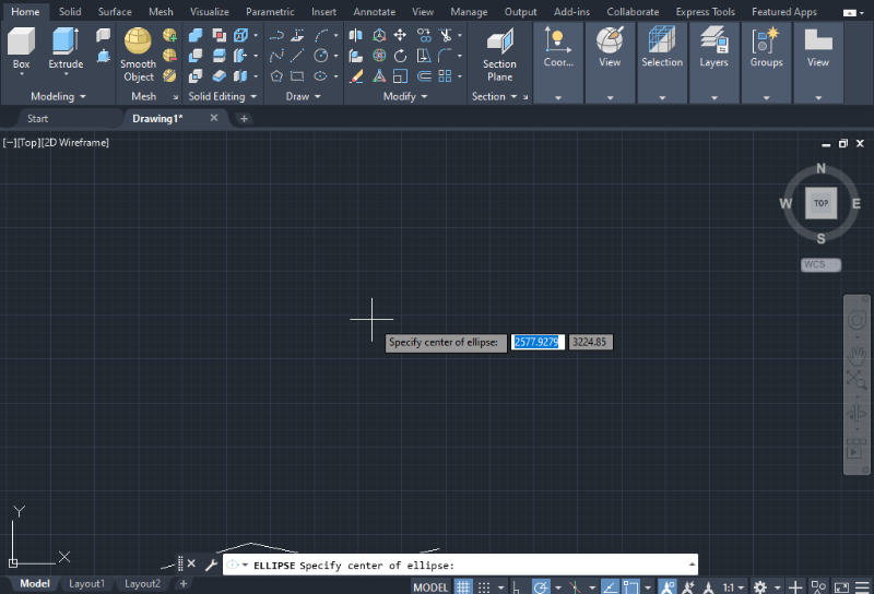
2. If you choose the Center option, you first need to establish the axis for the ellipse in terms of length and angle, which determines the horizontal size and orientation of the shape, as shown in the image below.
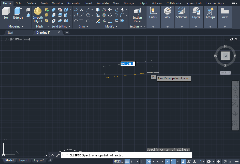
3. Then, AutoCAD will prompt you to provide the radius or distance for the vertical axis in order to complete the ellipse. Simply use the keyboard to type the desired length.
Hatch
In AutoCAD, the hatch tool enables users to fill objects or enclosed areas with specific patterns, colors, and textures. The sofWithin this new menu, users can control hatch properties, patterns, and boundaries.tware includes a library with various pre-designed hatch patterns that can be helpful. These patterns can be found in the Draw tab, below the Circle icon, with a drop-down menu displaying the available options: Hatch, Gradient, and Boundary.
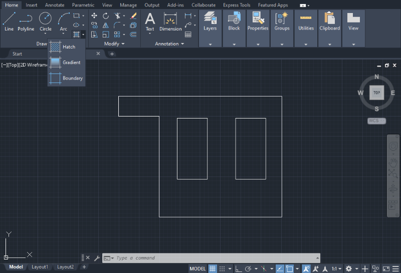
Gradients are used to provide a solid appearance to an object by filling the enclosed area with color, while boundaries only alter the visual aspect of the object’s contour or perimeter.
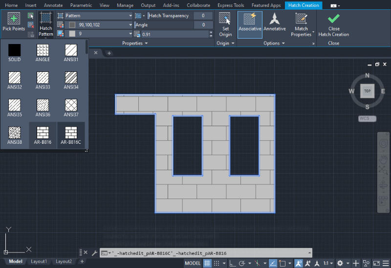
By selecting the Hatch Creation tab, a new set of tools will appear at the top of the screen, allowing users to modify and customize the hatch attributes according to their design requirements. Within this new menu, users can control hatch properties, patterns, and boundaries.
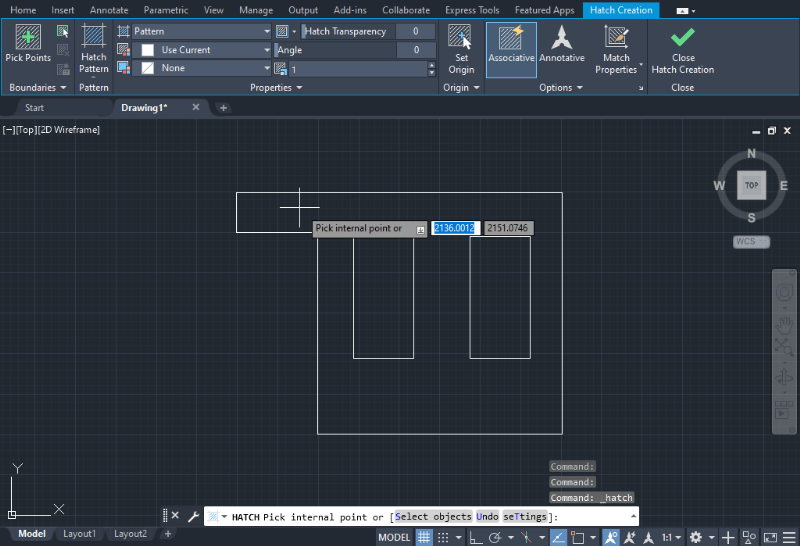
By clicking the Hatch pattern icon, users can choose from twelve available options.
Essential Modify Operations
The Modify tab in the top bar features a collection of icons representing essential operations for manipulating, modifying, and editing sketches in the workspace. These tools, including moving, copying, rotating, scaling, mirroring, trimming, exploding, extending, offsetting, chamfering, filleting, and stretching objects, are invaluable for designers and can be used both in two-dimensional and three-dimensional spaces. Below are guidelines for utilizing some of the most vital modification tools.
Move
The Move command enables users to relocate objects within the working space, regardless of the object’s original coordinates. It’s a vital tool for creating assemblies and is accessible in both the 2D environment (Draft and Annotations) through a cross arrow icon in the Modify tab, and the 3D environment (3D modeling) as MOVE 3D, indicated by a cross arrow with coordinate systems icon next to it.
Alternatively, you can access this command by simply typing “MOVE” in the Command bar and selecting the appropriate option based on your working environment (2D or 3D).
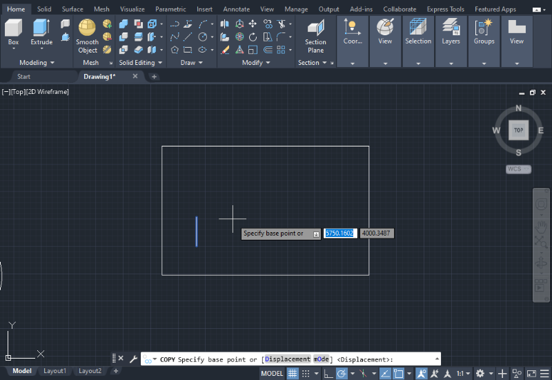
Copy
The Copy command can be found in the Modify section on the Home tab, as shown in the image below.
1. To duplicate an object, click the Copy icon and select the object you wish to copy.
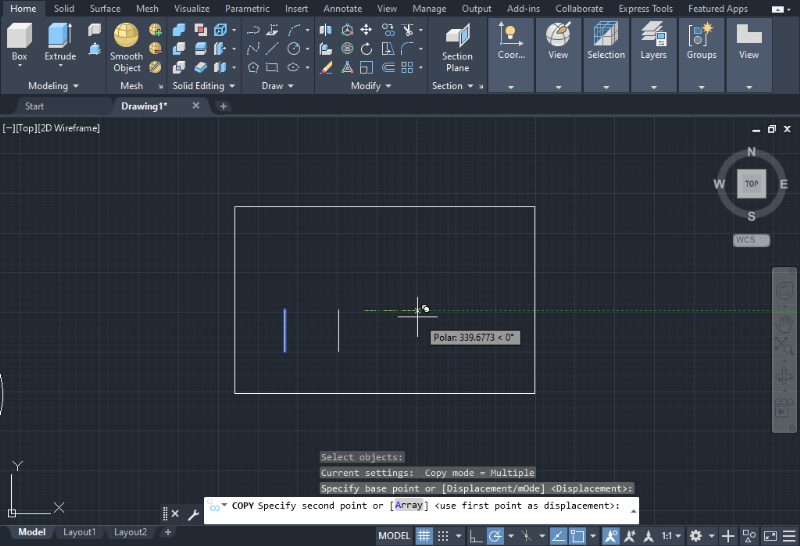
2. Then, specify the base point or coordinates where the copied object will be placed.
3. To create additional copies of the same object, click on any point in the workspace and define a new base point. Press the ESC key when you have completed the copying process.
Alternatively, you can also use the “ARRAY” command in the Command bar to duplicate a group of objects.
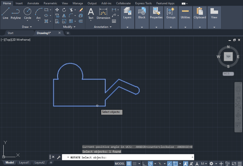
Rotate
The Rotate command enables users to change the position of an object by rotating it around a base point or a specified axis of rotation.
The Rotate icon is placed in the Modify tab on the Home tab, as shown in the image below.

You can also access this command by typing “ROTATE” in the Command bar at the bottom of the screen and pressing Enter.
1. To rotate an object, click the Rotate icon and select the object you wish to rotate, and press Enter.
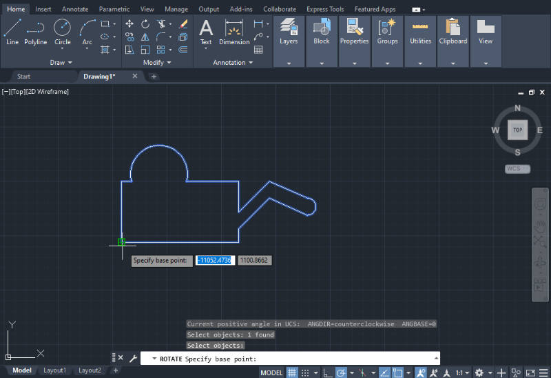
2. AutoCAD will prompt you to specify the base point or pivot point for rotation, as shown in the image below. Right-click to select the desired base point.
3. Next, determine the angle of rotation by either using the mouse or entering the angle value via your keyboard.
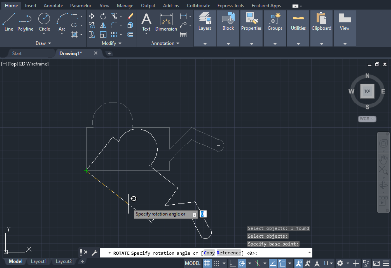
4. Once you have finished rotating the object, press the ESC key to exit the command.
Scale
A scaled drawing represents an object graphically, where each dimension is either enlarged or reduced in a specific proportion (scale). When working in the modeling section of AutoCAD, there are two methods available for scaling drawings: using a scale factor or a reference figure.
Scale Factor
If the scale is given or the ratio can be easily calculated (e.g., 1:2, 1:5, 3:1), the simplest approach is to type the scale factor.
1. Select the object(s) you want to scale.
2. Type “SCALE” in the Command bar and press Enter.
3. Choose a base point for the object.
4. Enter the scale factor and press Enter. If the number is between 0 and 1, it indicates scaling down, while a number greater than 1 represents scaling up.
Reference Figure
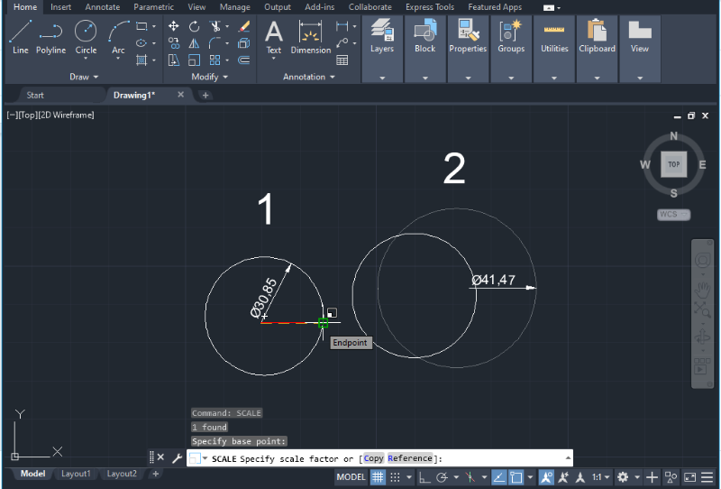
In some cases, the user may not know the scale factor or the calculated result may be a continuous number (e.g., 1.345876…) instead of an integer. In such situations, the user may be aware of the proportional size of the object or drawing in comparison to others. Other objects within the model space and images can serve as references. For example:
1. Figure 1 serves as the reference object, while Figure 2 is the one to be scaled. To scale Figure 1 to the size of Figure 2, draw a radius line from the center of Figure 1 to the edge of the circle. (shown as a red line).
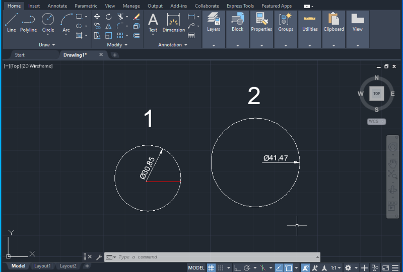
2. Select Figure 2, type “SCALE”, and press Enter.
3. Click on the center point of Figure 1 as the base point.
4. Click the end of the radius line as the scale factor.
5. Press Enter, and now the circles should have the same size.
Mirror
The Mirror command creates a mirrored copy of an object across a specific line, effectively creating its mirror image. The Mirror icon can be found in the top bar or accessed by typing “MIRROR” in the Command bar and pressing Enter.
1. To perform the Mirror function, click on the Mirror icon and select the entire object that you want to mirror. Make sure that all the lines of the object are highlighted in blue.
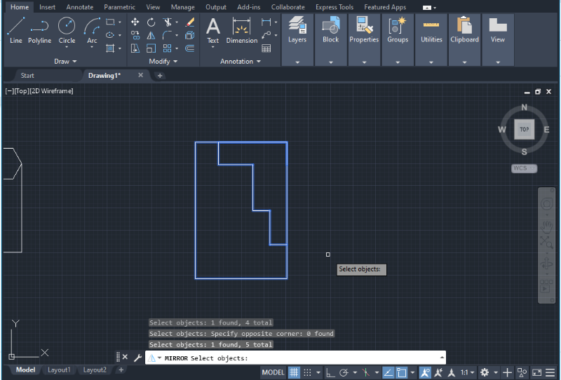
2. Next, AutoCAD will prompt you to choose the position for mirroring the object. If you want the mirrored object to be joined seamlessly, click on a corner that belongs to the boundaries of the object. This selected point will serve as the centerline of symmetry of the mirrored object.
3. After locating the mirroring position, press Enter, and a mirrored copy of the object will appear on the screen. You can use the mouse to rotate or move this new object within the workspace as needed.
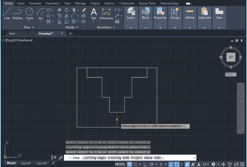
Trim
The Trim command allows users to selectively trim objects, lines, and shapes in their drawings. Users can choose to trim individual objects or select multiple objects by dragging the cursor or using the “Shift + Select” method.
To access the Trim command, simply click on the Trim icon located in the top bar or type “TRIM” in the Command bar at the bottom of the screen.
The Trim command is similar to the Erase command, as their icons are located next to each other. The main difference is that the Erase command deletes the chosen element from the drawing without considering the surrounding edges and geometry. However, in certain cases, they can be used interchangeably depending on the specific scenario.
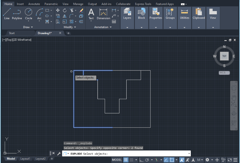
Explode
The Explode command enables users to edit and modify individual components of an object by breaking it down into its constituent elements. These elements can include lines, shapes, polygons, or areas.
1. To access the Explode command, simply click on the Explode icon located in the Modify tab or type the word “EXPLODE” in the Command bar.
2. Select the area or part of the object you wish to explode. The selected part will be highlighted in blue. Press Enter to execute the operation.
3. Each element of the selected area will be isolated from the main composite object. You can verify this by clicking on any point or line within the designated area.
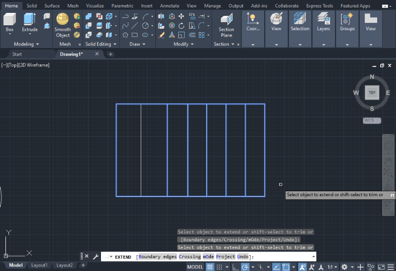
Extend
The Extend command is used to lengthen an object until it reaches the boundaries of another object. You can find the Extend command in the Modify section below the Trim option on the Home tab. Alternatively, you can execute this command by typing the word “EXTEND” in the Command bar.
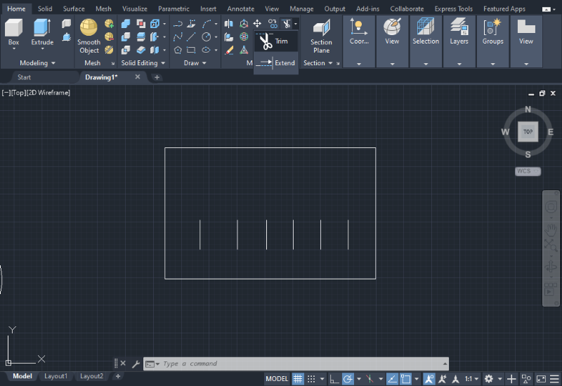
1. To extend lines, click on the Extend icon and select the lines you want to extend using the cursor, as shown in the image below.
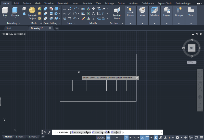
2. Once you click on a line, it will extend towards the nearest line or edge based on its orientation (vertical in this case).
3. If you want to specify specific boundaries for the extension, you can do so by clicking on the word “Boundary edges” in the Command bar, as shown in the image.

4. After selecting the objects you wish to extend, press Enter to complete the operation.
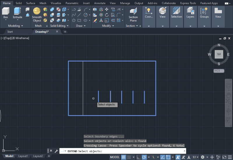
As a result, all the lines should be successfully extended, as illustrated in the example below.
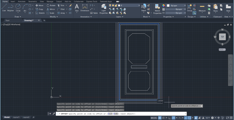
Offset
The Offset command is used to create concentric circles, parallel curves, and lines. It offers geometric versatility and can be applied to various closed figures, including squares, rectangles, and circles.
You can find the Offset command in the Modify options next to the Array icon on the Home tab. Alternatively, you can execute this command by typing “OFFSET” in the Command bar.
1. To begin, click on the Offset icon, select the object you want to offset, and press Enter.
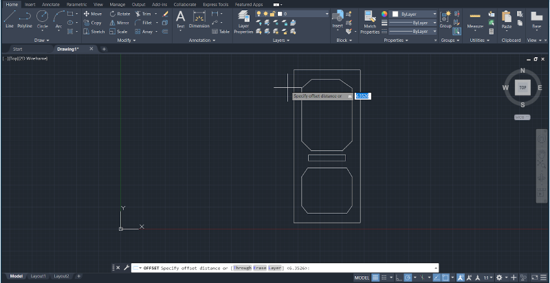
2. Next, specify the distance for the offset. It can be a positive or negative value relative to the original object.
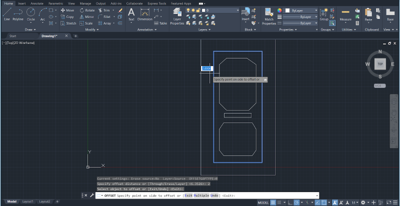
3. If you need to repeat the process multiple times with the same distance, you can select the “Multiple” option in the Command bar. This allows you to apply the established distance for subsequent offsets.
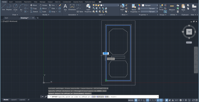
4. The number of offsets is determined by the number of right-clicks you make after selecting the “Multiple” option. Press the ESC key on your keyboard when you have completed the process.
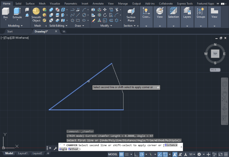
Chamfer
The Chamfer command allows for the joining of two lines or edges with a specific angle and distance, similar to the Fillet command but with an angular shape instead.
You can find the Chamfer command in the Modify options section below the Trim icon on the Home tab. Alternatively, you can type “CHAMFER” in the Command bar. Both the Fillet and Chamfer commands are located in the same menu.
1. To use the Chamfer command, select the Chamfer icon and click on the first line or edge you want to join.
2. Press Enter and then select the second line or corner to complete the operation. Press Enter again.
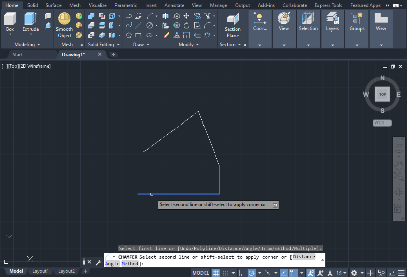
3. You can also adjust the angles or distances by clicking on the options highlighted in gray in the Command bar below.
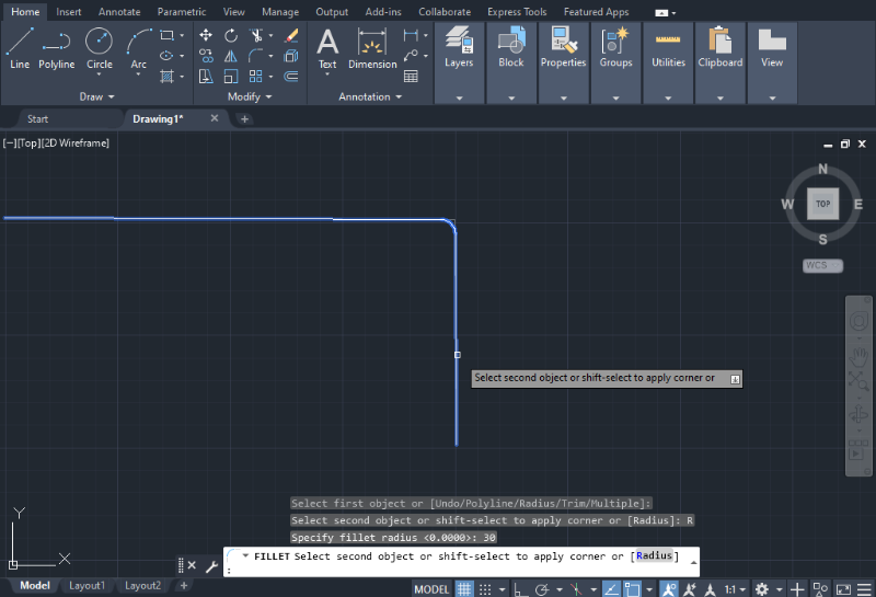
Fillet
The Fillet command involves connecting two lines with a round shape. It’s used to smooth corners and edges in 2D and 3D drawings. This tool is similar to the Chamfer command, but instead of creating a straight line, it creates an arc or round shape.
To use the Fillet command, you can follow these simple steps.
1. In the 2D environment, click on the Fillet icon located in the Modify Tab on the Home tab. Alternatively, you can type “FILLET” in the Command bar below and select the two objects you wish to fillet.
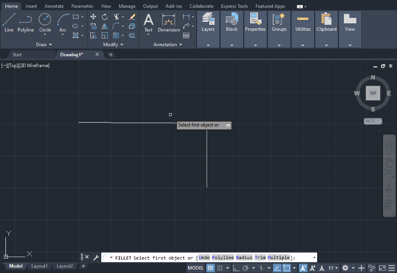
2. After selecting the objects, press Enter. The program will prompt you to enter the radius for the fillet operation. The default value is usually 0.0000.
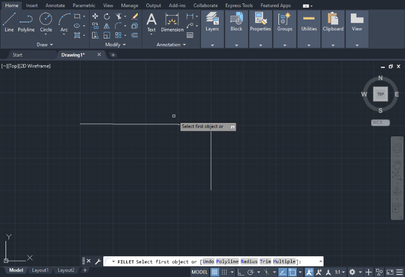
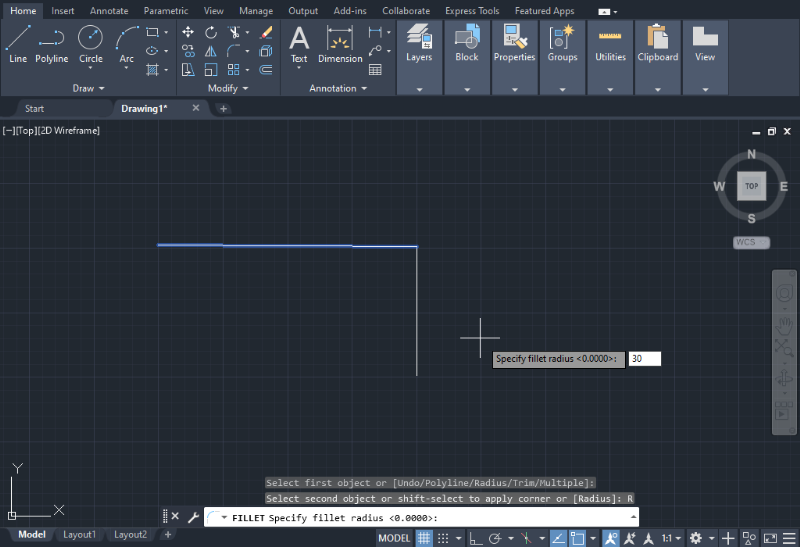
3. If the program doesn’t ask for the radius length, click on the word “Radius” highlighted in gray in the Command bar. Then, type the desired radius and press Enter.
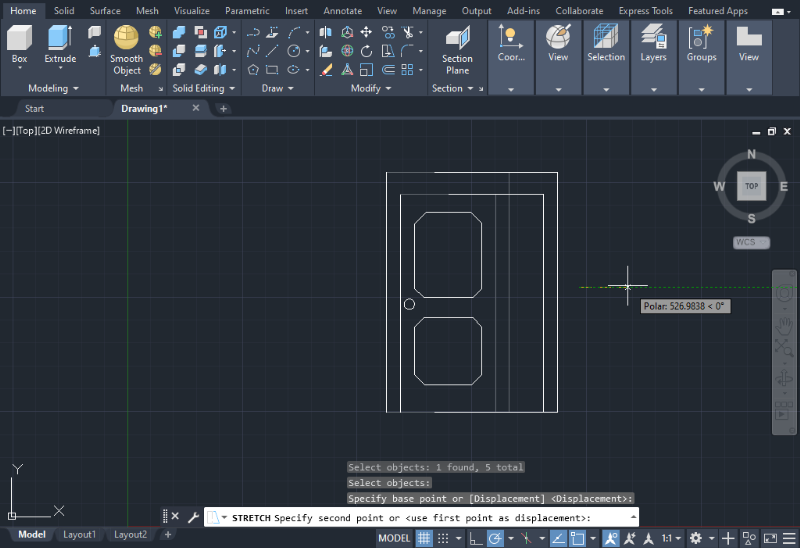
Stretch
The Stretch command is used to adjust the size or position of objects with partially enclosed areas or to move objects within the workspace.
Go to the Home tab and locate the Modify options section. The Stretch icon is located next to the Scale icon. Alternatively, you can type “STRETCH” in the Command bar at the bottom of the screen.
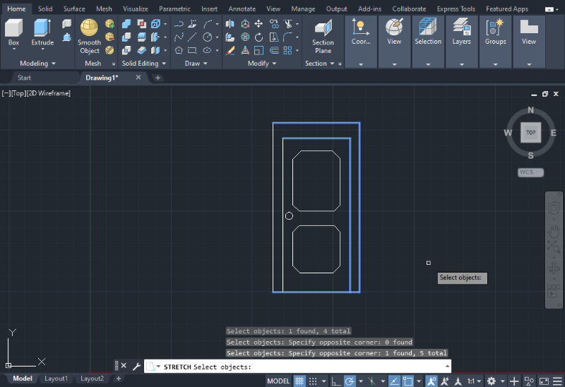
1. After selecting the Stretch icon, the program will prompt you to choose the lines you want to stretch.
Use the cursor to select the desired lines, as shown in the image below.
2. Next, select a coordinate in the workspace where you want to extend the lines to.
3. Press Enter to complete the Stretch operation. The object should now reflect the changes made during stretching.
Array
The Array command allows you to arrange objects or copies of them in a uniform distribution. You can choose between a rectangular array or array along a specified path, such as a polyline or rounded shape.
To access the Array command, go to the Home tab and locate the Modify options section. The Array icon is positioned below the Fillet icon. Alternatively, you can type “ARRAY” in the Command bar at the bottom of the screen and then select the desired Array type.
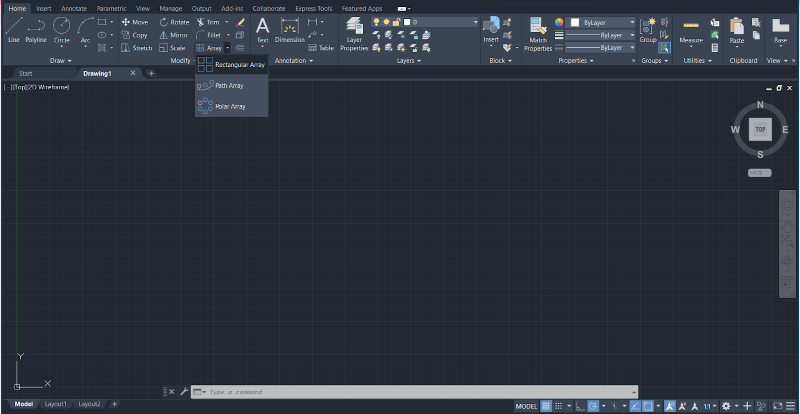
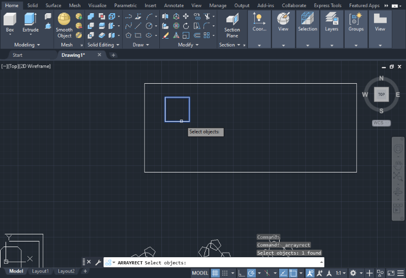
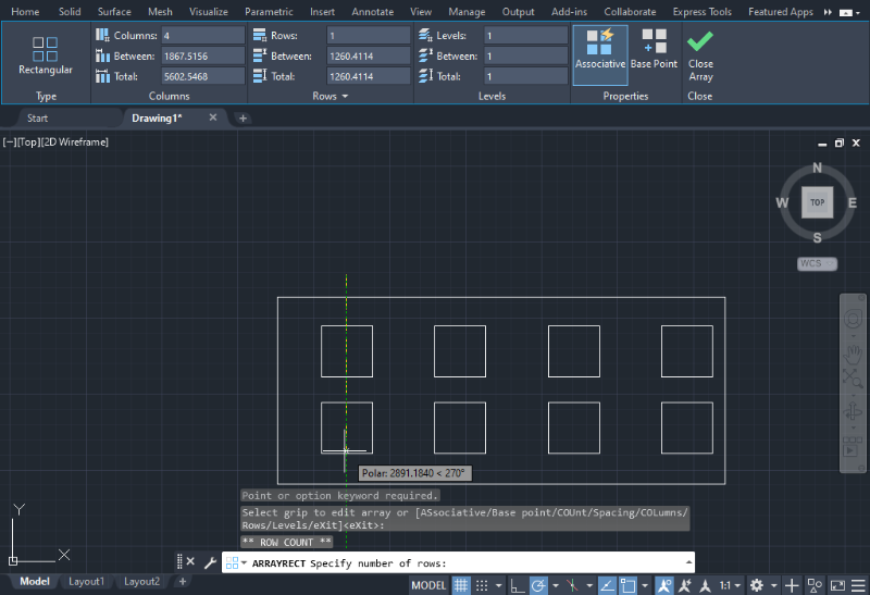
Rectangular Array
1. Select the rectangular array option. Use the cursor to choose the object you want to copy, which will serve as the pattern. Press Enter to confirm the selection.
2. A new set of options will appear at the top of the screen, allowing you to define the number of columns, rows, and the spacing between each object.
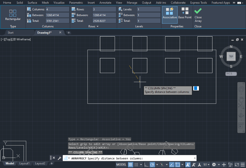
3. After setting the desired parameters, press Enter to complete the operation. You can also use the mouse to move the pattern within an enclosed area, as shown in the image below.
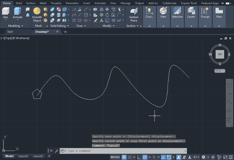
Path Array
1. To use the Path Array option, first, create a line or polyline and the shape that you want to transform into a pattern. In the provided example, a polyline and a pentagon are used.
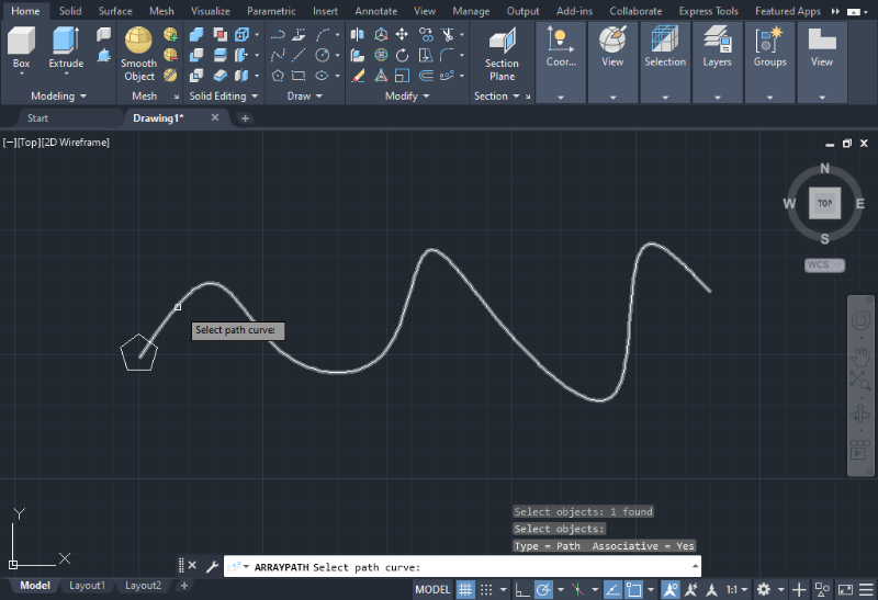
2. Select the Path Array option, then choose the path curve by selecting it with the cursor and pressing Enter.
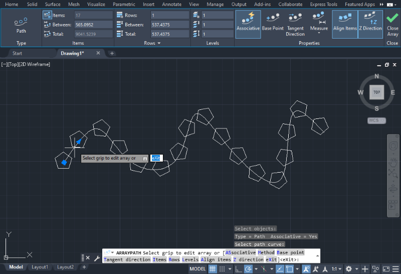
3. Next, select the object you want to create a pattern from. The program will immediately show the resulting array, highlighted in blue, as shown in the image below. Similar to the Rectangular Array, you can set the pattern parameters, including the number of repetitions and distance between each object.
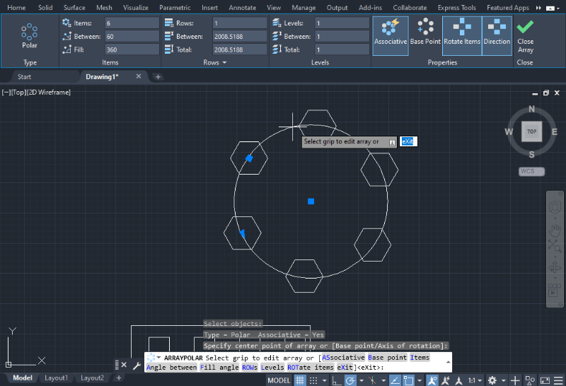
Polar Array
The Polar Array function follows a similar procedure as the Path Array, with the only distinction that the path is a circle or semicircle, as shown in the image below.
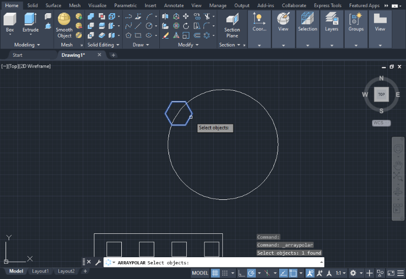
The parameter settings for the Polar Array are similar to the other Array types.
How to do 3DCAD with AutoCAD
From here, I will explain how to do 3DCAD with AutoCAD.
Extrude
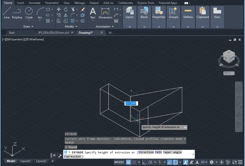
The Extrude command allows users to add the third dimension to a 2D drawing by providing a perpendicular height to the object. To perform the Extrude command, you can use the Extrude icon located in the Modeling options section on the Home tab. Alternatively, you can type “EXTRUDE” in the Command bar at the bottom of the screen.
1. Click on the Extrude icon, select the flat object (2D drawing) you want to extrude, and press Enter.
2. A dialog box will appear for entering the height of the body, which can be positive or negative depending on the axis. Alternatively, you can also use the mouse to establish the height. Then press Enter.
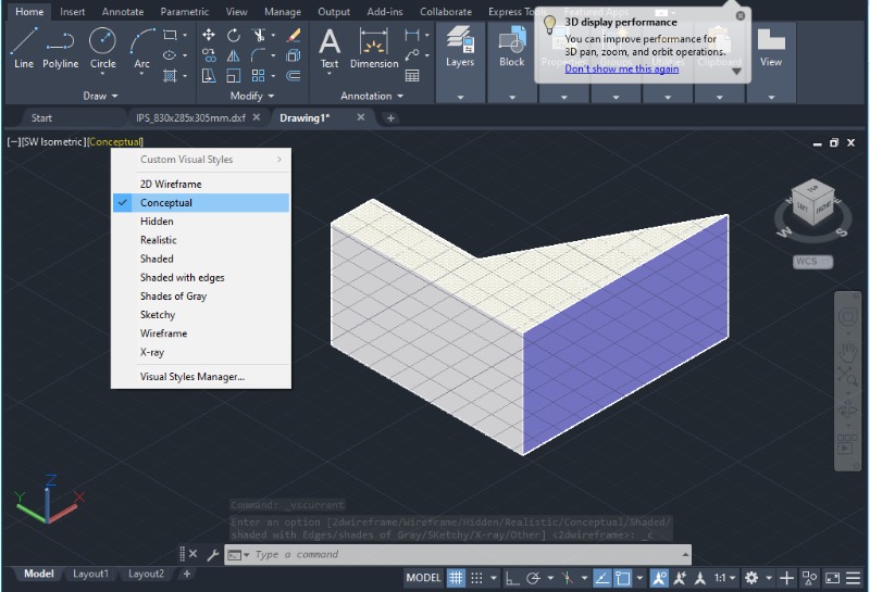
3. To customize the visual style of the model, click in the upper-left corner in the drawing space below the toolbar. This will allow you to change the object’s perspective, such as 2D wireframe, conceptual, realistic, etc.To customize the visual style of the model, click in the upper-left corner in the drawing space below the toolbar.
Revolve
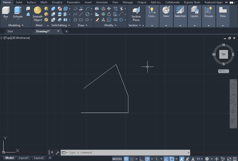
The Revolve command involves spinning an object around a specified axis enclosed by a 2D figure to create a symmetrical 3D model. Here are the steps to perform the Revolve command.
1. Create the shape of the object you want to revolve using a polyline or straight-line figure, as shown in the image below.
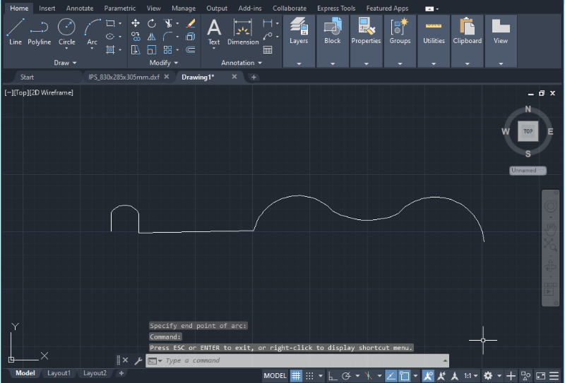
2. Ensure that the line or shape is open and joined.
3. In the Command bar, type “REVOLVE” and press Enter.
4. Click on the object you want to revolve and press Enter.
5. Indicate the axis of rotation by clicking in the working space. The rotation axis doesn’t necessarily need to intersect with the shape’s endpoints; it can be placed at any point in the drawing space. Then press Enter.

6. A dialog box will appear, allowing you to enter the revolution or spinning angle, ranging from 0 to 360 degrees. Alternatively, you can also use the mouse to establish the angle. Then press Enter.
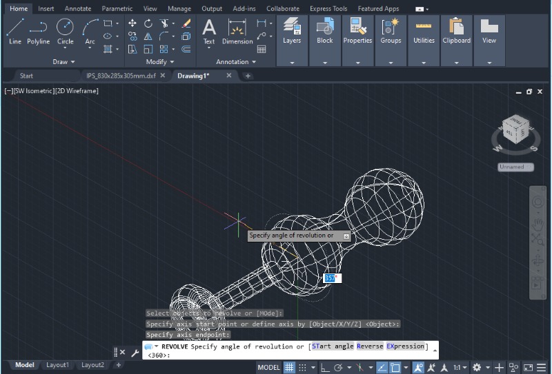
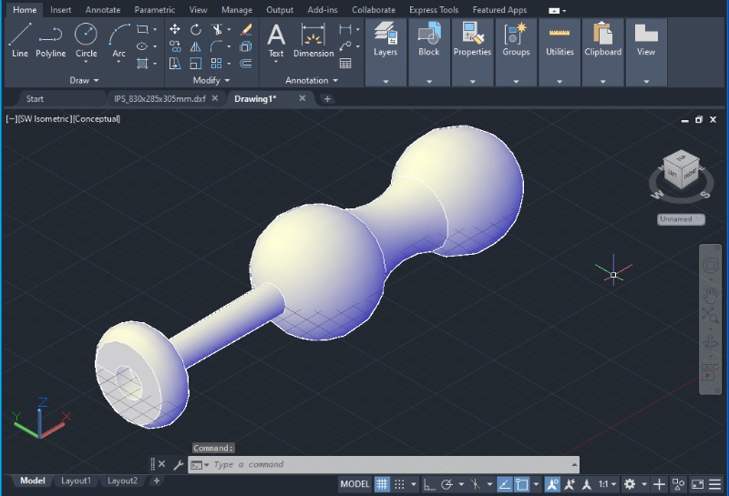
The revolved object will immediately appear as a conceptual body.
Sweep
This Sweep command is a useful tool for representing pipes and circuits based on an open or closed 2D path and a cross-section. Here’s how you can perform a sweep.
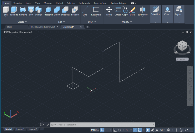
1. Begin by creating the open or closed path you want to sweep through. Use a polyline or straight-line figure, as shown in the image below.
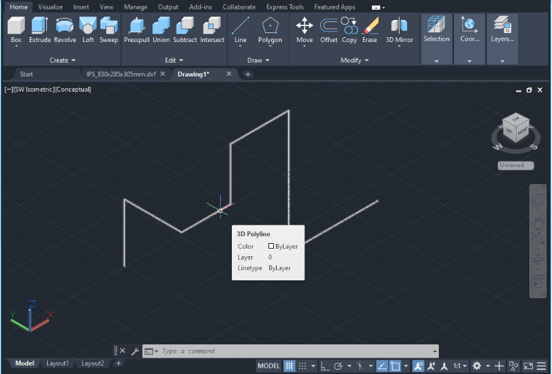
2. Next, create the cross-section that intersects with the endpoint of the path and is perpendicular to the path’s plane.
3. To ensure the correct alignment of objects in the drawing, switch to the Model View and verify that the cross-section is perpendicular to the 2D path. For example, the Top view model will face the cross-section.
4. In the Command bar, type “SWEEP” and press Enter. Alternatively, you can access the Sweep icon in the Modeling tab.
5. Select the cross-section and press Enter.
6. Select the path (the 2D polyline) and press Enter.
7. The solid will immediately appear in a conceptual view.
Loft
The Loft command allows users to join two 2D shapes and create a 3D model or surface within the space that separates them. Unlike extruding, this operation involves creating a solid between two distinct cross-sections. Here is how you can use the Loft command.
1. Ensure you have at least two 2D enclosed objects that are separated from each other along the axis perpendicular to the objects (typically the z-axis).
2. To verify the location of objects in the drawing, switch to the Model View and ensure that both objects are in the same plane. For example, the Top view should show both objects separated vertically.
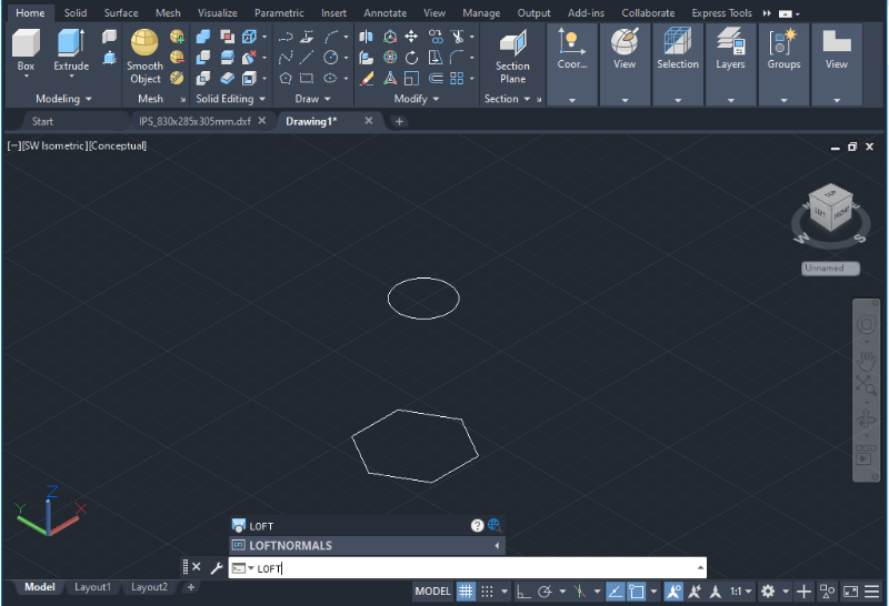
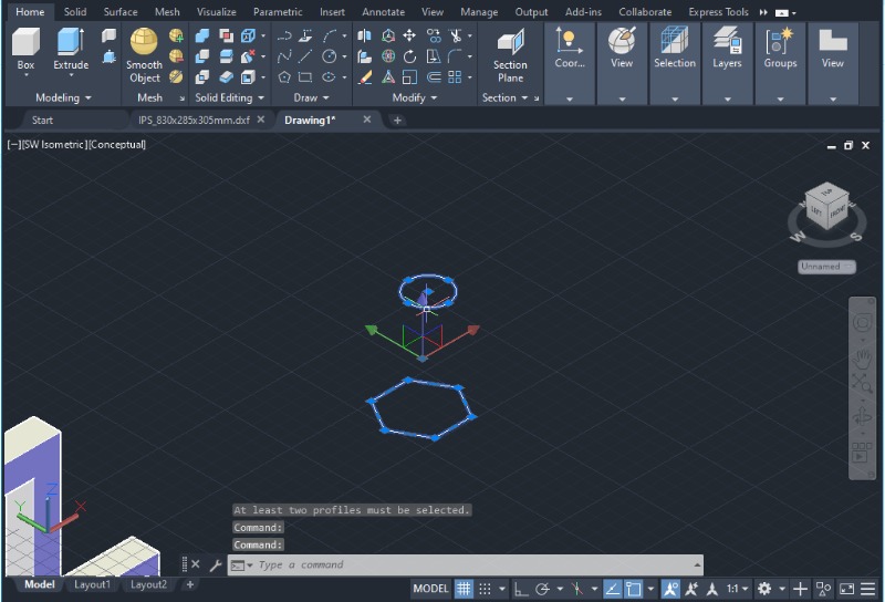
3. In the Command bar, type “LOFT” and press Enter. Alternatively, you can access the Loft icon in the Modeling tab.
4. Select the two desired objects, one after the other. As you select them, a coordinate system will appear on top of the cursor, indicating where the loft operation will occur. Press Enter to proceed.
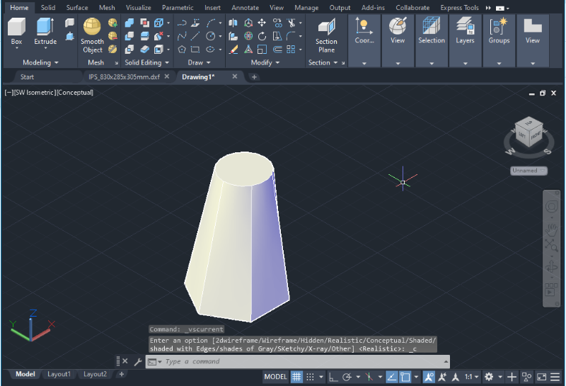
5. A solid will then appear in a conceptual view, as shown in the image below. You can always change the visual style of the solid by adjusting the settings.
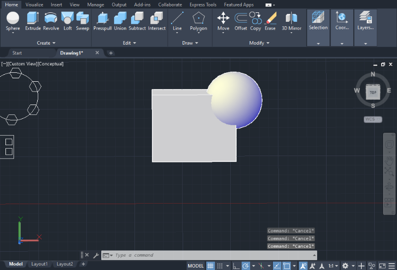
Boolean Operations
AutoCAD provides powerful boolean operations that allow users to manipulate and optimize solid designs. These operations, namely Union, Subtract, and Intersect, are available exclusively in the 3D basics and 3D modeling environments.
To access the boolean commands, navigate to the Modify section on the Home tab, located next to the Presspull icon.
Note: Ensure that you have a minimum of two objects to perform any boolean operation, whether it involves joining, subtracting, or intersecting them.
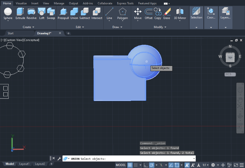
Union
1. Select the Union icon.
2. Use the mouse to select the objects you wish to join, and press Enter to complete the Union operation.
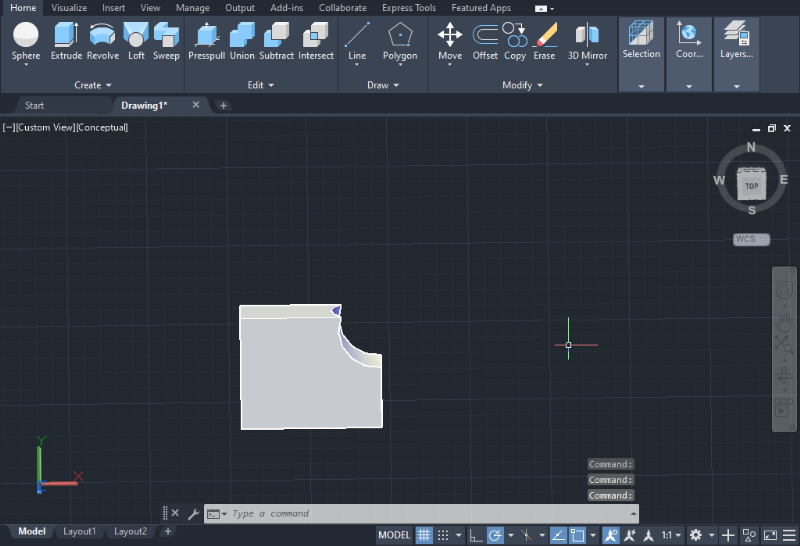
Subtract
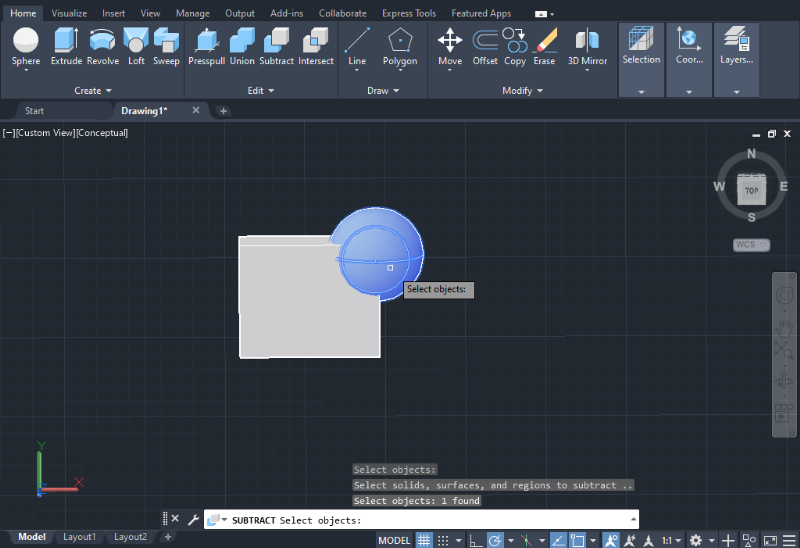
1. For the Subtract operation, begin by selecting the object you want to retain after the subtraction.
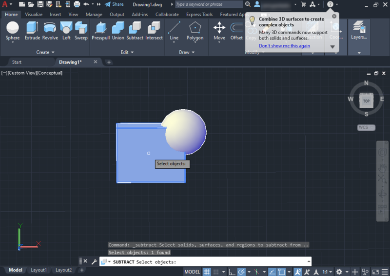
2. Next, select the object you want to eliminate, and press Enter to execute the Subtract operation.
For example, the result of our example looks like this:
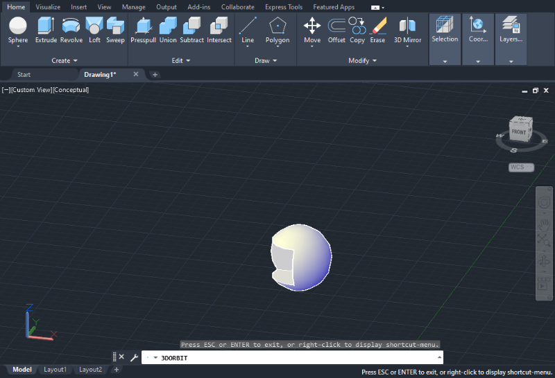
In case of choosing the other object (the sphere) first, the result will change to look like this:
Intersect
The Intersect operation functions similarly to the Union operation. The order in which you select objects does not matter.
1. After selecting the Intersect tool, use the mouse to choose the objects you want to intersect, and press Enter to finalize the Intersect operation.
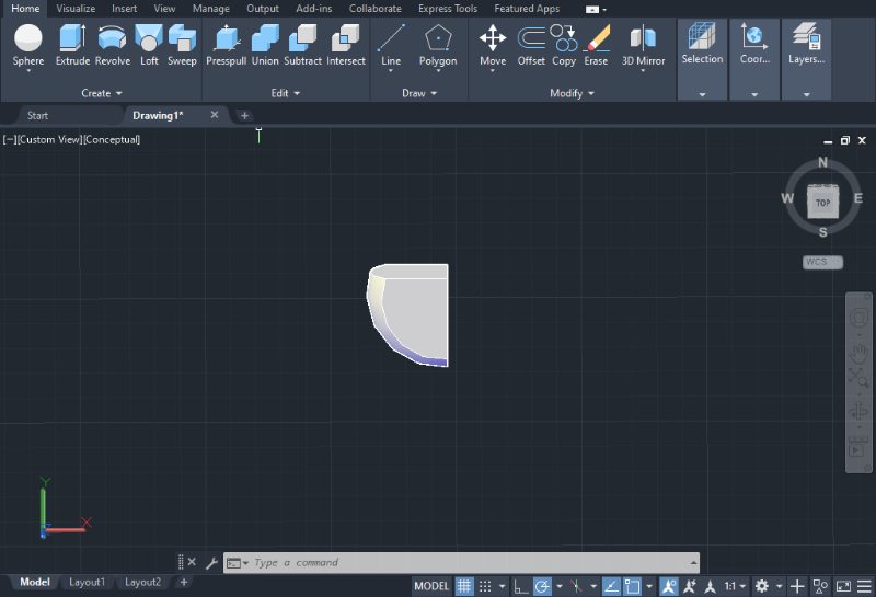
The resulting object will immediately appear on the screen, as shown in the image below.
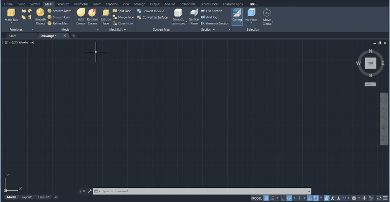
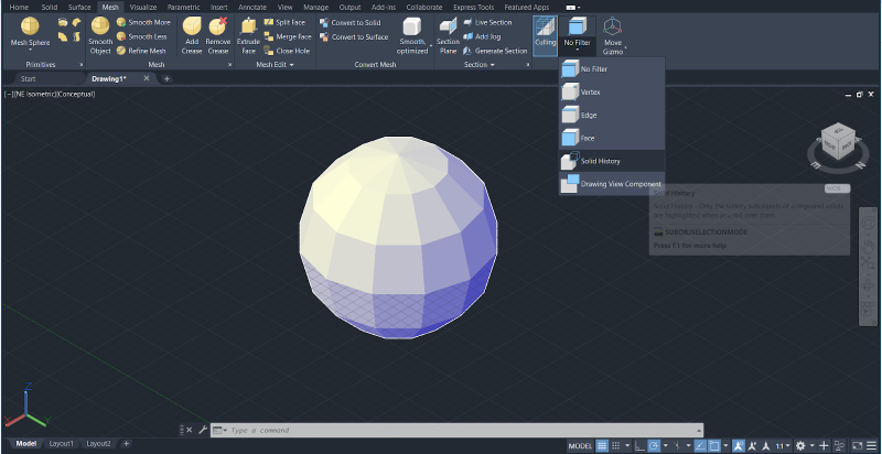
Working with 3D Meshes
A mesh is a 3D model composed of polygons with edges, faces, and vertices. Unlike solids, meshes are closed surfaces without mass.
In the 3D modeling environment, 3D meshes have their own tab with mesh editing tools, as shown in the image below.
Primitives
The simplest mesh tool is creating Primitives.
1. Choose one of the default primitives provided by AutoCAD, such as a box, cone, cylinder, sphere, wedge, or torus.
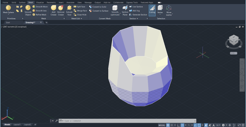
2. After selecting a primitive, you can use the mouse to adjust its size and start exploring the mesh editing tools.
3. Utilize the Selection section to manipulate the object’s vertices, faces, or edges. Each option allows you to modify specific parts of the mesh.
4. To flatten or extrude parts of the mesh, select the Face option.
5. Choose the faces you want to modify and use the Gizmo to move them along the x, y, or z axes.
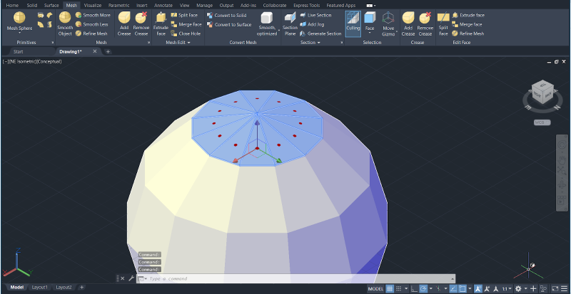
6. You can specify the height or distance by using the keyboard, and press Enter to complete the operation.
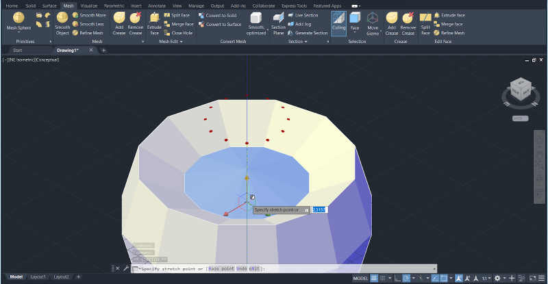
7. Switching to the Vertex option enables you to select one or multiple edges and move them within the workspace to shape the mesh. You can also establish a distance or height, as shown in the image below.
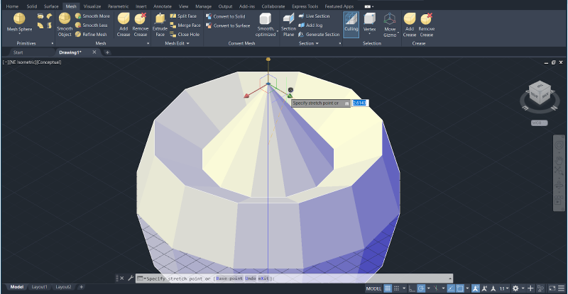
8. The process is similar when working with edges. Select the Edges option, click the edges you wish to manipulate, use the Gizmo to move them, and specify the distance.
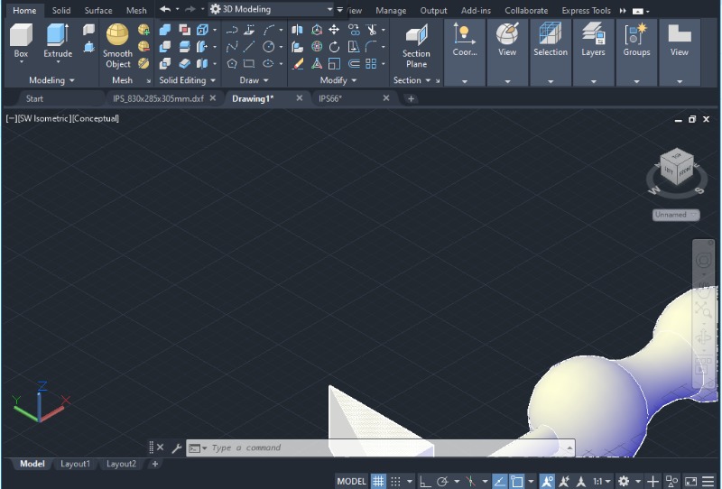
Convert to Solid
After familiarizing yourself with the basics of editing primitive meshes, converting the mesh into a solid is a useful option.
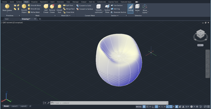
1. In the Convert Mesh tab, click on “Convert to solid” to transform the mesh into a solid, providing a smooth appearance to the object.
2. Select the mesh you want to convert and press Enter. The object should be transformed into a solid body with a smooth shape, as shown in the image below.
Working with Layers in AutoCAD
Layers are a useful feature in AutoCAD that helps users organize drawings by allowing them to temporarily suppress or hide unnecessary graphical data. Layers can be compared to clear, plastic sheets that contain information about the model, which can be overlapped to recreate all the details of a drawing. The Layer command serves various purposes in managing drawings, and becomes especially convenient when a sketch contains many objects and linetypes.
Creating New Layers
To create a new layer, follow these steps.
1. Click on the Layer Properties option on the main toolbar.
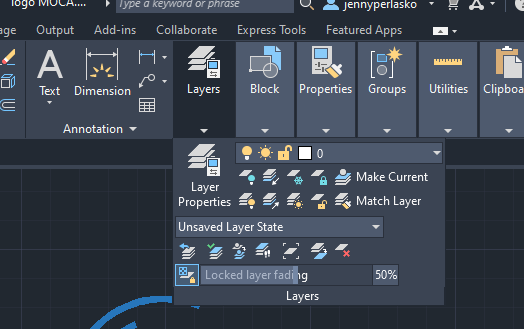
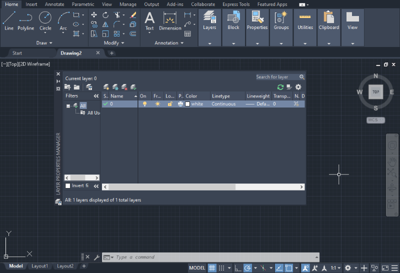
2. In the Layer menu, you will see a default layer named “0”. Layer 0 is the pre-established default layer for all drawings and typically contains some default properties. To create a new layer, click on the icon that has a yellow star.
3. From the Quick Access menu options, select the properties you want to incorporate into the new layer by clicking once in each cell. These properties can include the layer name, linetype, color, thickness, and visibility.
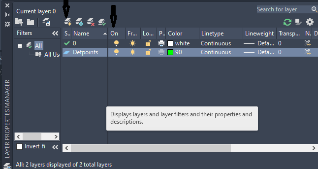
4. Use the Lightbulb icon to toggle the visibility of a layer, turning it on or off.
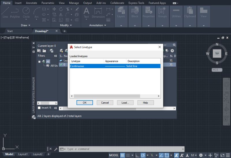
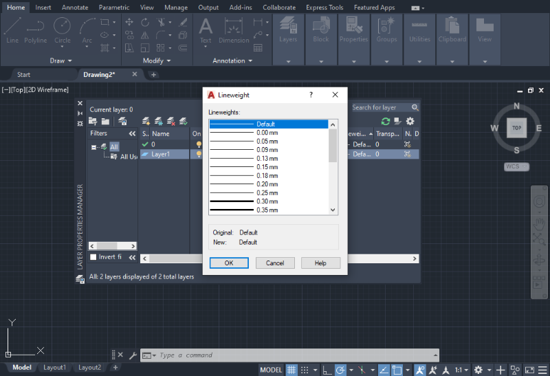
Changing Layer Properties
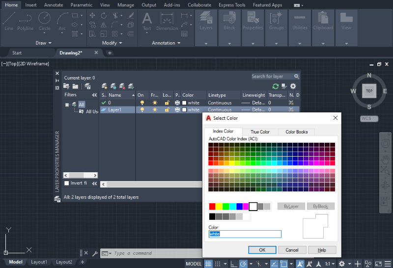
1. In the Draft and Annotation environment, click the down arrow below the Layers icon and select the Layer Properties as shown in the image below.
2. A new window will immediately appear on the screen, displaying all existing layers and their associated parameters (such as color, linetype, lineweight, etc.).
3. To modify a parameter, click on the default value below each parameter and follow the provided instructions for each case, as shown in the images below. Press Enter after modifying each parameter.
Annotations and Dimensions
Annotations and Dimensions allow AutoCAD users to provide important information about the design.
Annotations
1. To display annotations in the workspace, navigate to the Annotation tab in the top bar and click on the Linear Dimension icon, located next to the Dimension icon. From the drop-down menu, select the annotation type, such as linear, aligned, angular, or radius, depending on the element you want to annotate in the drawing.
2. After choosing the annotation type, click the starting measuring point, then select the ending point, and press Enter.
3. The annotation will appear on the screen, and you can adjust its position by dragging it with the mouse, keeping in mind the space required for other annotations.
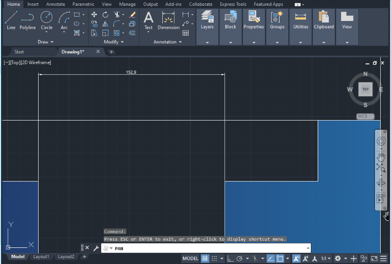
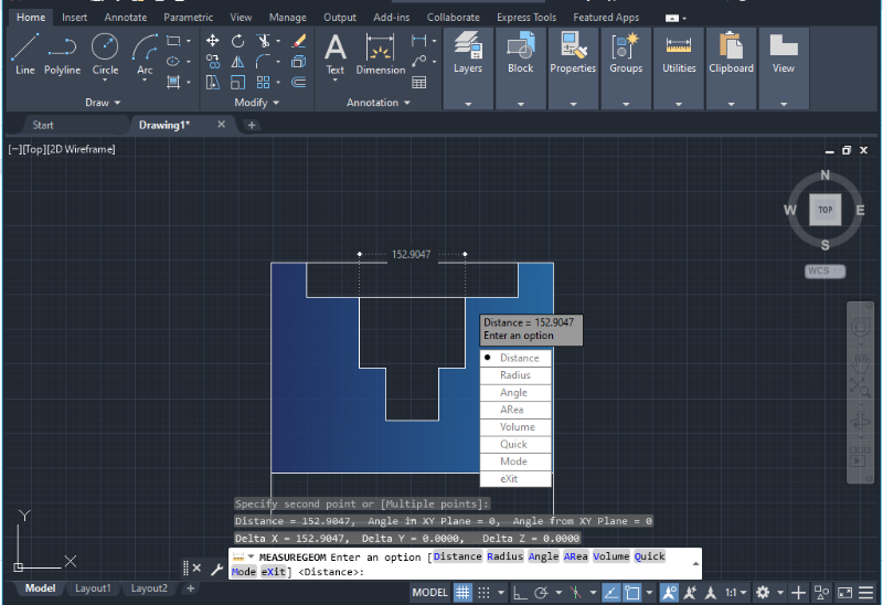
Dimensions
The Dimension icon, also found in the Annotation tab, is a valuable tool for verifying measurements in a drawing. It displays the dimensions of specific parts of the sketch temporarily and offers options to measure radii, angles, volumes, and areas of objects.
The process of measuring an object is similar to annotations, with the difference that once the dimension is shown on the screen, it will disappear after pressing Enter.
This tool is particularly useful for checking dimensions without cluttering the drawing with excessive annotations.
Dimension Styles (DimStyle)
Dimension Styles, often referred to as “DimStyles”, are collections of settings that control the appearance of dimensions in a drawing. It’s possible to create and modify these collections in AutoCAD.
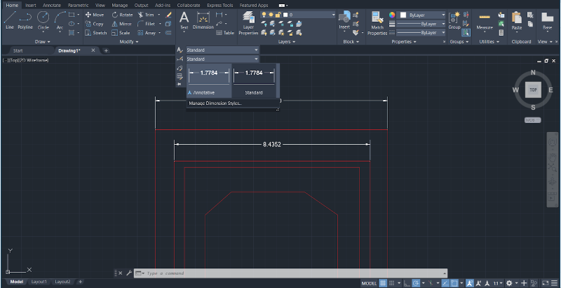
1. To change the DimStyle in the Model space, access the Annotation tab and click the drop-down menu to display the annotation options, as shown in the image below. Click on the second row in the drop-down menu next to the word “Standard” to access the Dimension Style Manager.
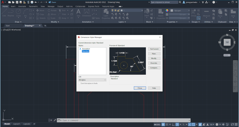
2. A new window will immediately appear to create, modify, or compare DimStyles. Select the “New” option if you are setting the dimension style for the first time, and select “Modify” to change the parameters of an existing DimStyle.
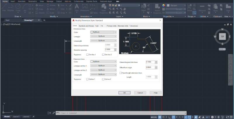
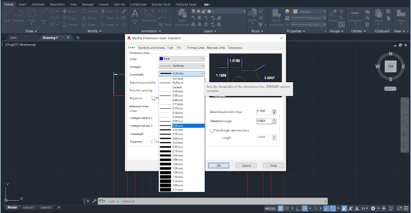
If you select the “Modify” option, a new section will appear with different parameters for you to adjust, such as Color, Linetype, Lightweight, and others, as shown in the image below.
The current DimStyle will be displayed at the top right, and the preview will update as you modify the parameters.
You can also change the units for the dimensions and customize tolerances, formats, and fonts to create a custom DimStyle.
3. Once you have made all the desired changes, select “OK”.
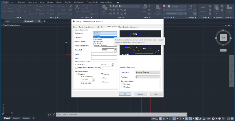
If you select the “Modify” option, a new section will appear with different parameters for you to adjust, such as Color, Linetype, Lightweight, and others, as shown in the image below.
Using AutoCAD Beyond Its Basic Functions
This article on how to use AutoCAD covers the program’s most essential commands and operations, including basic drawing tools, mesh editing, working with layers, annotations, and more. By incorporating these functionalities into your daily AutoCAD processes, you can enhance the organization, accuracy, and efficiency of your designs.
As you continue your AutoCAD training, working in the three-dimensional space will be an important step. Therefore, mastering these basics in the two-dimensional space is crucial to prepare yourself for more advanced tools that can fully unlock AutoCAD’s three-dimensional capabilities.