AutoCAD’s Extrude command converts 2D shapes into 3D shapes by adding the missing dimension through a positive or negative length. The extrusion allows the creation of a new solid while maintaining the original geometry of the 2D surface. Extruding is a common design tool in AutoCAD’s 3D Basics and 3D Modeling environment instead of the Draft and Annotations environment that is set by default.
Extruding Surfaces in AutoCAD
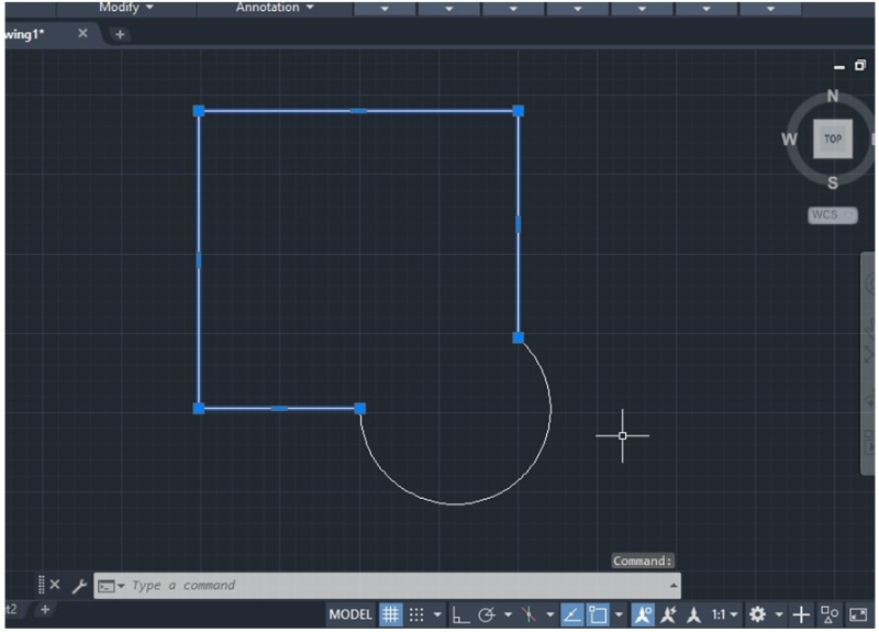
To extrude a surface and generate a 3D body in AutoCAD, you need to have a closed object and join all the lines that enclose the shape. Extruding is not possible with an open object.
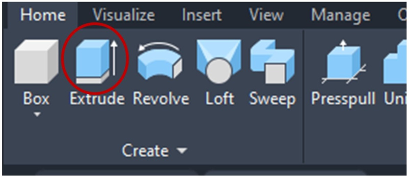
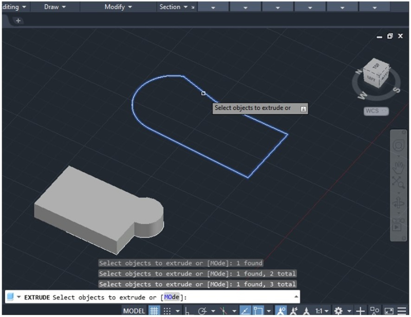
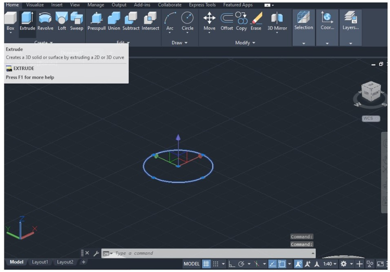
1. To extrude the surface, you can type the word “Extrude” in the command bar or select the Home toolbar in the 3D Basics environment and click the Extrude icon.
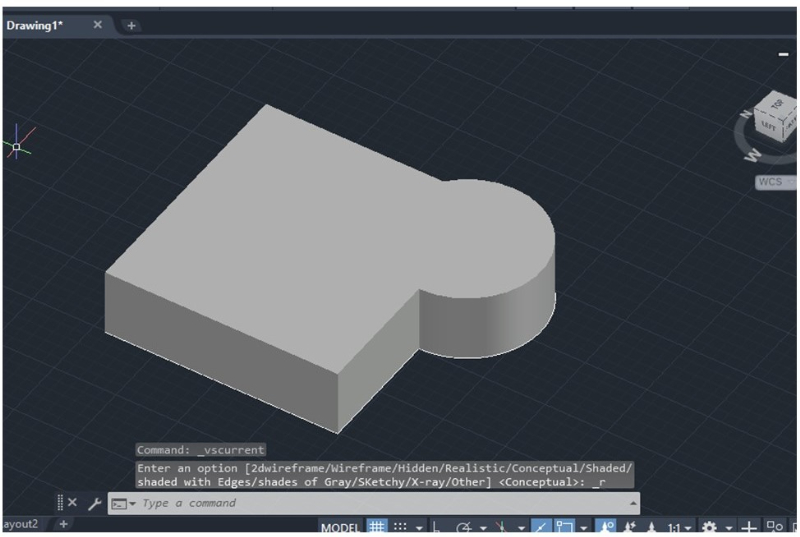
2. Next, select the object you want to extrude and establish the height (positive or negative). Then press Enter to finish the operation.
3. You can customize the view of the model by selecting the Custom Visual Styles menu located in the upper-left part of the workspace.
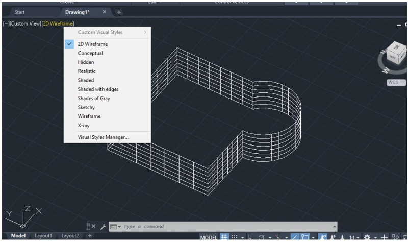
“2D Wireframe” is the view set by default when working in the Drafts and Annotations environment, while “Realistic” is usually the default view for the 3D Basics environment.
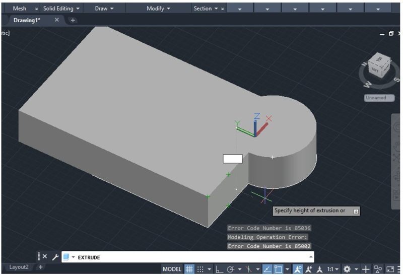
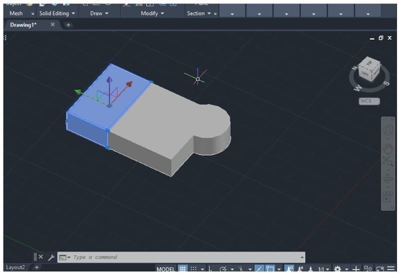
You can also extrude one of the faces or areas from an extruded object. To do this, select which face you want to extrude and specify the height as shown in the pictures below.
Extruding Hollow Objects
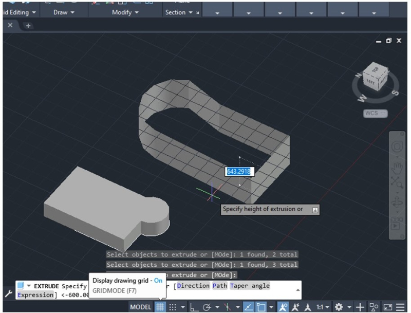
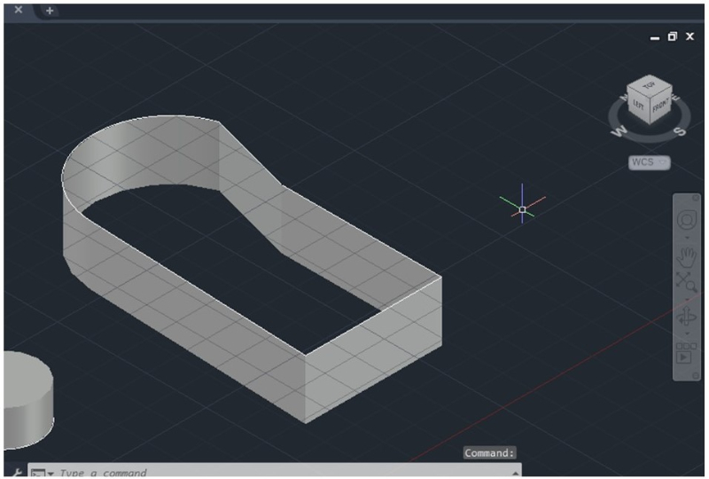
Extruding only the contour of a body can be necessary in certain circumstances. This means the extruded object will be hollow, similar to a Shell command.
To do this, you need to extrude an object whose constitutive lines are not joined, meaning you will be extruding lines instead of surfaces or areas. However, the width of each face or wall of the object will be limited to the line’s width. You can only control the height of the extrusion but not the width.
Extruding with Taper Angle
The Extrude command lets you control the direction, height, and angle of the extrusion.
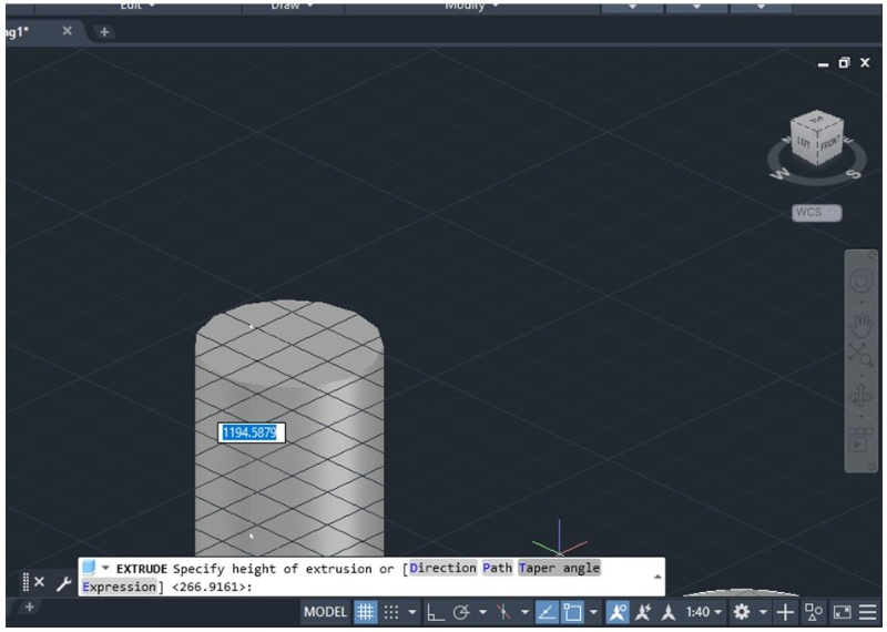
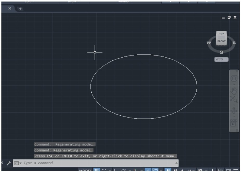
1. To achieve a tapered angle, you need to have a surface and select the Extrude command.
2. Next, the command bar will display the Extrude command with written instructions. The words “Direction, Path, Taper angle, and Expression” will be highlighted in gray as shown in the picture below.
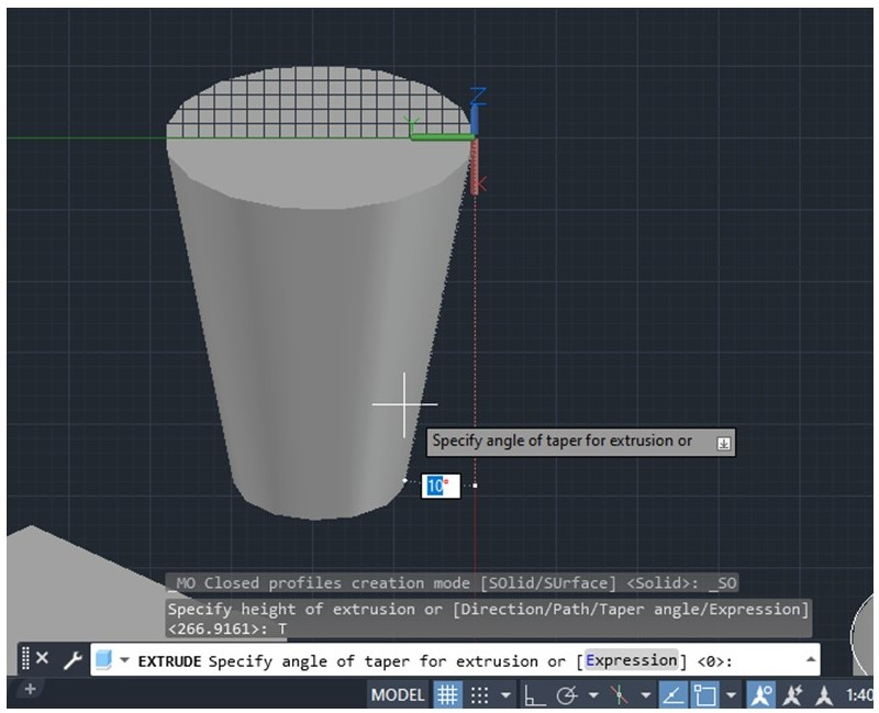
Click on “Taper angle” to specify the extruding angle needed. Then press Enter.
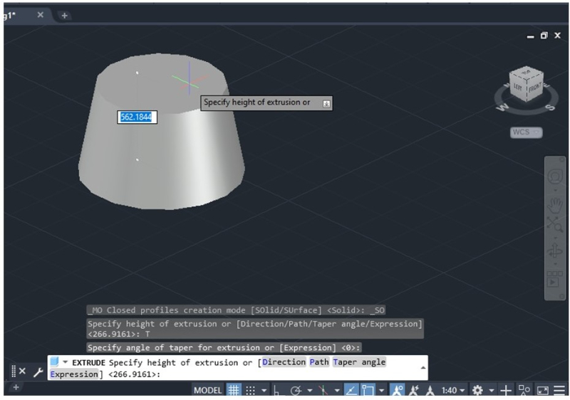
3. Finally, you can specify the extrusion height or click one of the other options (path or direction). Press Enter after setting the extrusion height.
Extruding along a Direction or Path
The Extrude command offers the opportunity to extrude along a direction or path. This direction should not be parallel to the standard extruding angle, meaning the angle should be above or below 90 degrees, using the original surface as a reference.
1. Any shape can be extruded following a specific direction. It’s advisable to draw the shape and use the ViewCube to create a line perpendicular to the original shape.
After changing the model view, it will be easier to draw a line that will dictate the direction of the extrusion as shown in the picture below.
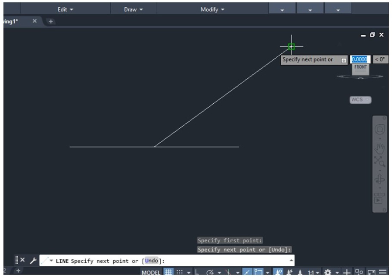
2. Specify the length and angle of the line and press Enter. Now the object is ready to be extruded.
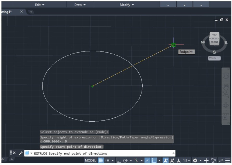
3. Select the Extrude command in the Home toolbar or type the word “Extrude” in the command bar and select the object to be extruded. Then press Enter.
4. Click the Direction option highlighted in gray in the command bar. Select the starting point and endpoint of the line you previously created. Then press Enter.
The extruded object should appear immediately as shown in the picture below.
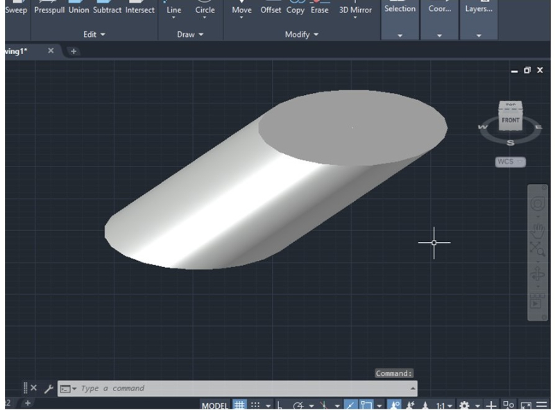
Extruding along a path is similar to extruding along a direction, with the difference being that the path can be a polyline or arc. The rest of the process follows the same steps.
Extruding Text
Extruding text can be useful when working with 3D models in AutoCAD. To achieve this, it’s necessary to transform the 2D text into a 3D shape with AutoCAD’s Express Tools.
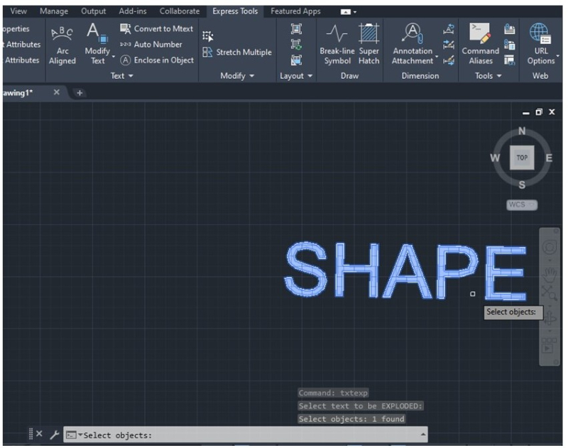
1. First, choose the text you want to extrude with the desired font and style. Once you have it, access the Express Tools tab and click the Modify Text drop-down menu in the Text section. A menu will appear with a set of options. Then select Explode.
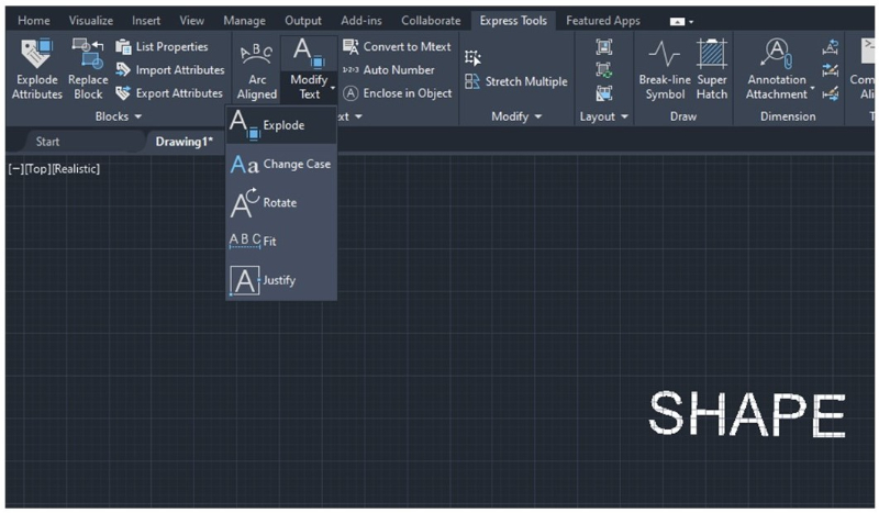
Make sure the model view is (0,0,1) before using the Explode Text tool. This means the ViewCube should be placed on Top to use this tool.
2. Select the text you want to explode using the cursor and press Enter.
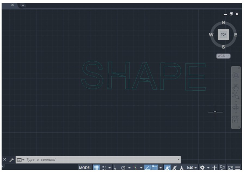
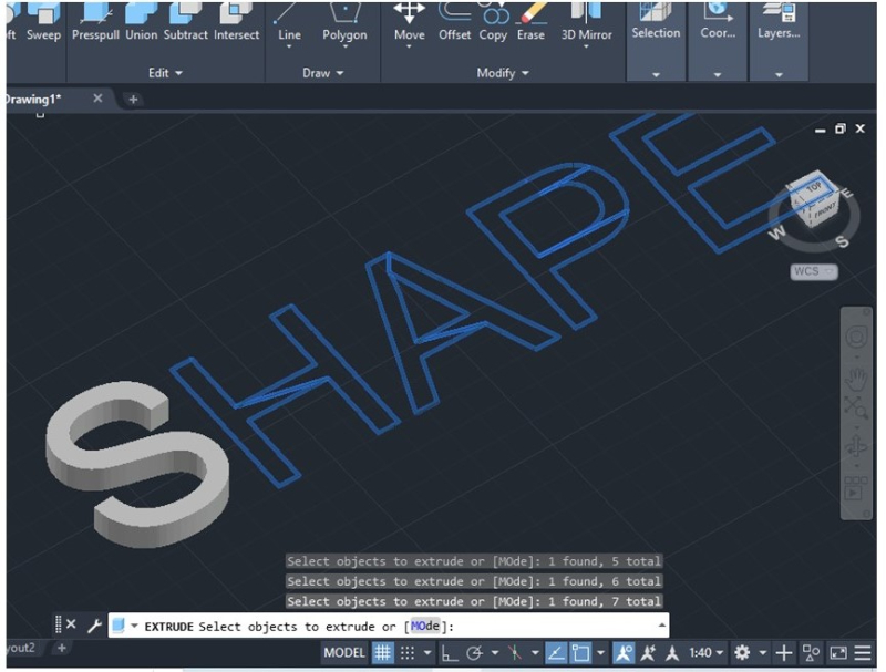
The text will change to contour each letter with green lines as shown in the picture below. Now the text is ready to be extruded with the standard Extrude command.
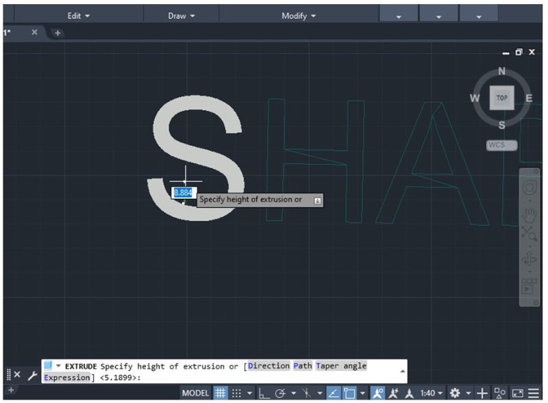
3. Click the Home toolbar and select Extrude. AutoCAD will ask you to select an object to extrude. Select the text and press Enter.
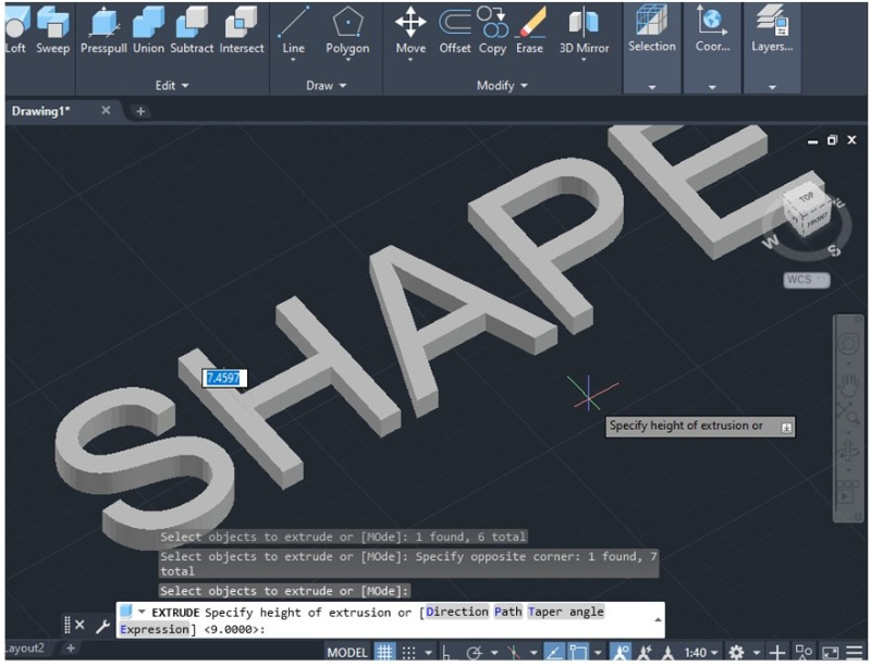
4. Indicate the height of the text and press Enter. The text will appear with a gray fill if working in a “Realistic” view.
You can use the ViewCube again to change the text’s perspective and see the final result as shown in the picture below.
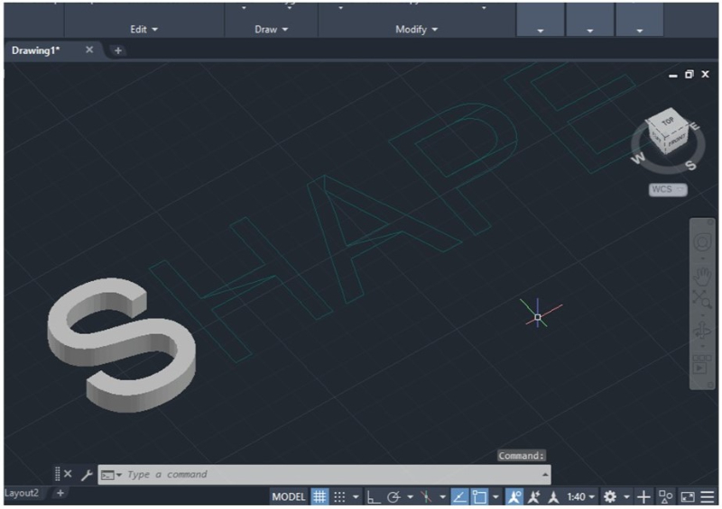
To avoid repeating this process for each letter, you can select all lines and extrude them at once as shown in the image below.
In addition to what is shown above, you can establish a positive or negative height for the text, just like the standard Extrude command.
Lastly, extruded text can be placed on an object previously extruded or a solid model by placing the letters in one of the faces of the solid model and following the same steps explained above.